Top side/Side view
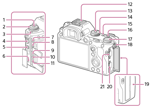
- Drive mode dial lock release button
- Upper: Drive mode dial
Lower: Focus mode dial - Focus mode dial lock release button
- LAN terminal
-
 (Flash sync) terminal
 - Speaker
-
 (Microphone) jack
When an external microphone is connected, the built-in microphone turns off automatically. When the external microphone is a plugin-power type, the power of the microphone is supplied by the camera.
-
 (Headphones) jack
 - HDMI micro jack
- Charge lamp
- Multi/Micro USB Terminal*
This terminal supports Micro USB-compatible devices.
- Multi Interface Shoe*
Some accessories may not go in all the way and protrude backward from the Multi interface shoe. However, when the accessory reaches the front end of the shoe, the connection is completed.
- Mode dial lock release button
- Mode dial
- C2 button (Custom button 2)
- C1 button (Custom button 1)
- Exposure compensation dial
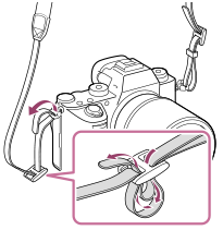
- Hooks for shoulder strap
Attach both ends of the strap onto the camera.
-
 (N mark)
- This mark indicates the touch point for connecting the camera and an NFC-enabled Smartphone.
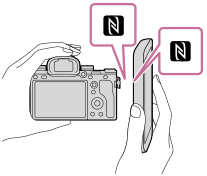
- NFC (Near Field Communication) is an international standard of short-range wireless communication technology.
- This mark indicates the touch point for connecting the camera and an NFC-enabled Smartphone.
- SLOT 1 (Memory card slot 1)
Supports SD cards only (compatible with UHS-I and UHS-II)
- SLOT 2 (Memory card slot 2)
Supports SD cards (compatible with UHS-I) and Memory Stick PRO Duo media
* For details on compatible accessories for the multi interface shoe and the Multi/Micro USB Terminal, visit the Sony website, or consult your Sony dealer or local authorized Sony service facility. Accessories for the Accessory Shoe can also be used. Operations with other manufactures’ accessories are not guaranteed.


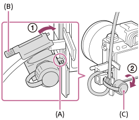
To attach the cable protector
Use the cable protector to prevent the HDMI cable from being disconnected when shooting images connected by the HDMI cable. Open both of the jack covers and insert an HDMI cable into the camera. Swing the HDMI micro jack cover downward and attach the cable protector as illustrated so that the end of the cable protector fits in the slit (A) under the Multi/Micro USB Terminal. Secure the cable protector with the attachment screw (B). Then secure the HDMI cable with the fixing dial (C).