Identifying parts
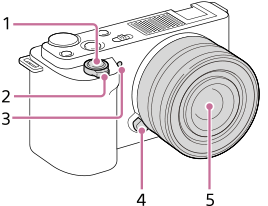
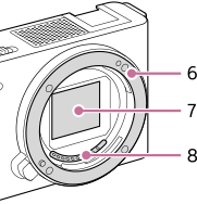
When the lens is removed
- Shutter button
- For shooting: W/T (zoom) lever
For viewing: (Index) lever/Playback zoom lever
 - Self-timer lamp/Recording lamp
- Lens release button
- Lens
- Mount
- Image sensor*
- Lens contacts*
*Do not directly touch these parts.
- ON/OFF (Power) switch
- Internal microphone*
- Multi Interface Shoe**
-
 Image sensor position mark
- The image sensor is the sensor that converts light into an electric signal. The position of the image sensor is indicated by (Image sensor position mark). When you measure the exact distance between the camera and the subject, refer to the position of the horizontal line.

- If the subject is closer than the minimum shooting distance of the lens, the focus cannot be confirmed. Make sure you put enough distance between the subject and the camera.
- The image sensor is the sensor that converts light into an electric signal. The position of the image sensor is indicated by
- Hooks for shoulder strap
Attach both ends of the strap onto the camera.

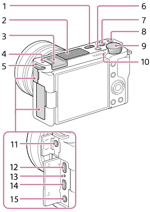
- Still/Movie/S&Q button
- MOVIE (Movie) button
- C1 button (Custom button 1)/
 (Background Defocus) button
 - Control dial
- Wi-Fi/Bluetooth antenna (built-in)
-
 (Microphone) jack
When an external microphone is connected, the built-in microphone turns off automatically. When the external microphone is a plugin-power type, the power of the microphone is supplied by the camera.
- USB Type-C terminal**
- Charge lamp
- HDMI micro jack
-
 (Headphones) jack
*Do not cover this part during movie recording. Doing so may cause noise or lower the volume.
** For details on compatible accessories for the Multi Interface Shoe and the USB Type-C terminal, visit the Sony website, or consult your Sony dealer or local authorized Sony service facility. Accessories for the Accessory Shoe can also be used. Operations with other manufactures’ accessories are not guaranteed.


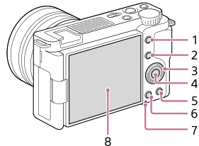
- MENU button
- For shooting: Fn (Function) button
For viewing: (Send to Smartphone) button
You can display the screen for [Send to Smartphone] by pressing this button.
- Control wheel
- Center button
-
 (Delete) button/
 (Product Showcase Set) button
 -
 (Playback) button
 - Access lamp
- Monitor/Touch panel
- You can adjust the monitor to an easily viewable angle and shoot from any position.
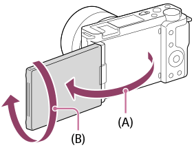
(A): Approx. 176°
(B): Approx. 270° - You may not be able to adjust the monitor angle depending on the type of a tripod you use. In such a case, release the tripod screw once to adjust the monitor angle.
- Do not apply excessive force when opening, closing, or rotating the monitor. Doing so may cause a malfunction.
- You can adjust the monitor to an easily viewable angle and shoot from any position.
- Connection plate cover
- Use this when using an AC-PW20 AC Adaptor (sold separately). Insert the connection plate into the battery compartment, and then pass the cord through the connection plate cover as shown below.

- Make sure that the cord is not pinched when you close the cover.
- Use this when using an AC-PW20 AC Adaptor (sold separately). Insert the connection plate into the battery compartment, and then pass the cord through the connection plate cover as shown below.
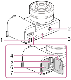
- Tripod socket hole
Supports 1/4-20 UNC screws
Use a tripod with a screw less than 5.5 mm (7/32 inches) long. Otherwise, you cannot firmly secure the camera, and damage to the camera may occur.
- Speaker
- Battery/memory card cover
- Memory card slot
- Battery insertion slot
- Battery lock lever
Using the wind screen (supplied)
Use the wind screen to reduce wind noise picked up by the internal microphone when recording a movie.
Attach the wind screen to the Multi Interface Shoe.

Note
- When attaching the wind screen, make sure that the wind screen does not get caught in the Multi Interface Shoe.
- When attaching a lens, make sure that the wind screen does not get caught in the lens mount.