

Parts and Controls
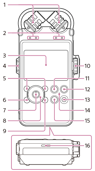
Front
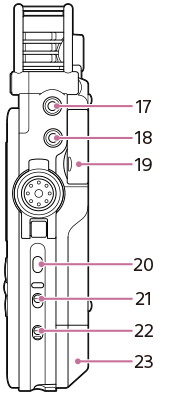
Right side
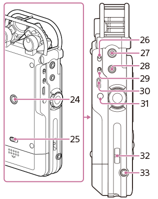
Left side
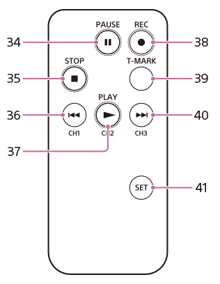
Remote control (transmitter unit)
-
Built-in microphones
-
Peak level lamps (L/R)
Displays left and right peak levels of the audio signal input with -12dB (green) and OVER (red) lamps.
-
Display window
-
VOLUME dial
Adjust the playback volume by turning the dial to set the desired level (0 to 10) to the “—” position next to the display window.
-
F1/F2 (function key 1/2) buttons
Frequently used functions can be assigned to these buttons.
-
HOME/BACK button
-
 (play/enter) button (*1)
 -
Control button (
 (up),
(up),  (down),
  (review/fast backward),
  (cue/fast forward))
 -
OPTION button
-
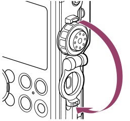
REC LEVEL (recording level) dial
Adjust the recording volume by turning the dial to set the desired level (0 to 10) to the “—” position next to the display window.
To adjust the right and left channels simultaneously, turn the external dial. To change the balance of recording levels between the right and left channels, turn the inner dial while pressing and holding it.
About the REC LEVEL dial guard
To prevent unintentional operations, please close the REC LEVEL dial guard. Open the REC LEVEL dial guard to adjust the volume.
-
 PAUSE button/indicator
 -
 REC (recording) button/indicator
 -
T-MARK (track mark) button
-
ACCESS indicator
Flashes when the recorder is accessing memory.
-
 STOP button
 -
Built-in speaker
-
MIC (microphone) jack
-
LINE IN(OPT) (line input (optical)) jack
-
Memory Stick™/SD card slot (*2)
-
LIGHT button
Turns the backlight of the display on or off.
-
POWER switch
Turns the power “ON” or “OFF.”
-
HOLD switch
-
Battery compartment cover
-
Hole for mounting a tripod (not supplied)
-
Battery cover lock lever
-
INPUT switch
When set to MIC (microphone), built-in microphones or an external microphone that is connected to the MIC jack are recorded.
When set to LINE, the audio signal output from external equipment that is connected to the LINE IN(OPT) jack is recorded.
-
LINE OUT(OPT) (line output (optical)) jack
-
 (headphones) jack
 -
MIC ATT (microphone attenuator) switch
-
 USB connector
 -
DC IN 6V jack
-
Slot for wrist strap
(Wrist strap is not supplied.)
-
REMOTE jack
-
PAUSE button
-
STOP button
-
(review/fast backward) /CH1 (channel 1) button
-
PLAY/CH2 (channel 2) button
-
REC (record) button
-
T-MARK (track mark) button
-
(cue/fast forward) /CH3 (channel 3) button
-
SET button
Press and hold the SET button and press CH1, CH2, or CH3 to set a channel to the remote control.
*1 Buttons have a tactile dot that can be used a reference point for operations, or to identify each button or jack.
*2 In this Help Guide, Memory Stick™ and SD cards are generally referred to as “memory card.” The Memory Stick™/SD card slot is referred to as the “memory card slot.”