Top side/Side view
-
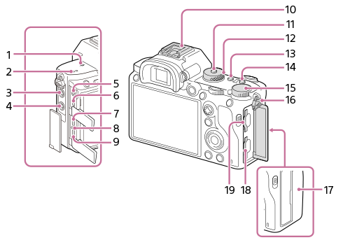
 Image sensor position mark
- The image sensor is the sensor that converts light into an electric signal. The mark shows the location of the image sensor. When you measure the exact distance between the camera and the subject, refer to the position of the horizontal line.
- If the subject is closer than the minimum shooting distance of the lens, the focus cannot be confirmed. Make sure you put enough distance between the subject and the camera.
- The image sensor is the sensor that converts light into an electric signal. The
- Speaker
-
 (Microphone) jack
When an external microphone is connected, the built-in microphone turns off automatically. When the external microphone is a plugin-power type, the power of the microphone is supplied by the camera.
-
 (Flash sync) terminal
-
 (Headphones) jack
 - HDMI micro jack
- USB Type-C terminal
- Charge lamp
- Multi/Micro USB Terminal*
This terminal supports Micro USB-compatible devices.
- Multi Interface Shoe*
Some accessories may not go in all the way and protrude backward from the Multi interface shoe. However, when the accessory reaches the front end of the shoe, the connection is completed.
- Mode dial lock release button
- Mode dial
- C2 button (Custom button 2)
- C1 button (Custom button 1)
- Exposure compensation dial
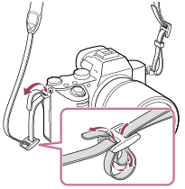
- Hooks for shoulder strap
Attach both ends of the strap onto the camera.
-
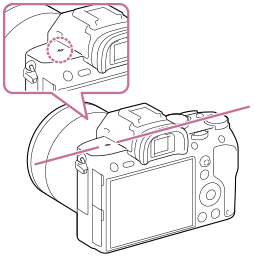
 (N mark)
- This mark indicates the touch point for connecting the camera and an NFC-enabled Smartphone.
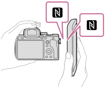
- NFC (Near Field Communication) is an international standard of short-range wireless communication technology.
- This mark indicates the touch point for connecting the camera and an NFC-enabled Smartphone.
- SLOT 1 (Memory card slot 1)
Supports SD cards only (compatible with UHS-I and UHS-II)
- SLOT 2 (Memory card slot 2)
Supports SD cards (compatible with UHS-I) and Memory Stick PRO Duo media
* For details on compatible accessories for the multi interface shoe and the Multi/Micro USB Terminal, visit the Sony website, or consult your Sony dealer or local authorized Sony service facility. Accessories for the Accessory Shoe can also be used. Operations with other manufactures’ accessories are not guaranteed.


Notes on USB terminals
You can use either the USB Type-C terminal or the Multi/Micro USB Terminal for supplying power, charging the battery, and USB communications. However, you cannot conduct these operations with both terminals simultaneously.
- The battery charging time does not change according to the terminal you use.
- You can use accessories for the Multi/Micro USB Terminal, such as a remote commander (sold separately), while supplying power or performing PC Remote shooting using the USB Type-C terminal.
Notes on the cable protector
Use the cable protector to prevent a cable from being disconnected when shooting images with the cable connected.
To attach the cable protector
- Thread the cable through the cable protector.
- Open both of the jack covers on the monitor side and insert the cable into one of the jacks.
- Fit the hook of the cable protector into the slit under the Multi/Micro USB Terminal (A).
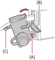
- Attach the cable protector as illustrated so that the upper jack cover fits into the notch in the cable protector (B), and then insert the claw of the cable protector into the slit next to the HDMI micro jack.
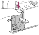
- Push the attachment screw (C) in and turn it to secure the cable protector.
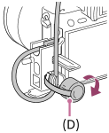
- Insert the cable into the holding part and then secure the cable with the fixing dial (D).
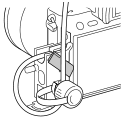
- You can pull the upper jack cover out of the cable protector, and stabilize the cover under the cable as illustrated below.
- You can pull the upper jack cover out of the cable protector, and stabilize the cover under the cable as illustrated below.
To remove the cable protector
Loosen the attachment screw. Push down the upper part of the cable protector and pull it out as illustrated.