Identifying the parts
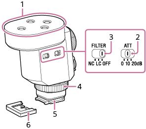
Top, Side, and Bottom
-
Microphone
-
ATT switch
Select the option suitable for the audio recording volume. To record loud sounds while minimizing distortion, select “20dB.” To record quiet sounds, select “0dB.” It is recommended that you select an option while monitoring the volume level meter on the camera or the audio recording volume with headphones.
-
FILTER switch
NC: Select this option to use the noise cut filter function. Unpleasant noises are effectively eliminated by digital signal processing. If the sound quality does not seem appropriate, select “OFF.”
LC: Select this option to use the low cut filter function. Unwanted noises, such as wind noise, air-conditioning noise, and vibration noise, are minimized.
OFF: Select this option to disable either of the filter functions.
Note
-
Hand-held use of the attached camera in a quiet place may cause a soft vibrating sound to be recorded.
If the recorded vibrating sound is disturbing, set the FILTER switch to “LC” and try all over again.
-
-
Lock dial
-
Multi Interface foot
Note
- Do not touch the connector of the Multi Interface foot with bare hands.
-
Connector protect cap
Back, Side
-
USB Type-C® port (for maintenance and service use)
Note
- No power is supplied through the USB Type-C port. Do not connect any device, such as a mobile battery pack, to the port for power supply purposes to avoid a malfunction.
-
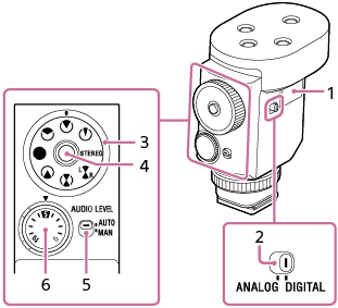
DIGITAL/ANALOG switch
Select the digital or analog input type.
-
If your camera is compatible with the digital audio interface of the Multi Interface Shoe, set the switch to “DIGITAL.”
Digital signal transmission between this unit and the camera has the following merits over analog signal transmission that is enabled by the DIGITAL/ANALOG switch being set to “ANALOG.”
-
Audio recording with less noise
-
Less audio delay during recording
-
Recording with 24-bit audio (only available in combination with the compatible camera)
-
Recording with channel 3 and channel 4 (only available in combination with the compatible camera)
Note
- Movies recorded with 24-bit audio may not be played back normally on devices or software incompatible with 24-bit audio, resulting in unexpectedly loud volumes or no sound.
-
-
If your camera is not compatible with the digital audio interface of the Multi Interface Shoe, set the switch to “ANALOG.”
When the message “This accessory is not supported by the device and cannot be used.” is displayed on the camera, set the switch to “ANALOG.”
If this does not help, see here.
-
-
Directivity mode dial
 : Super-directional
 : Uni-directional
 : Omni-directional
 : Super-directional (Rear)
 : Super-directional (Front+Rear)
 : Super-directional (Front/Rear) separate
 : Stereo
 : Ultra-directional
 -
Lock button
Pressing this button locks/unlocks the directivity mode dial.
-
AUTO/MAN switch
AUTO: The recording volume level is automatically adjusted.
MAN: Adjust the recording volume with the AUDIO LEVEL dial.
-
AUDIO LEVEL dial
The recording volume level can be adjusted manually for fine tuning when the AUTO/MAN switch is set to “MAN.”
It is recommended that you adjust the level while monitoring the volume level meter on the camera or the audio recording volume with headphones.
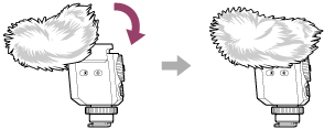
About the wind screen
By fitting the wind screen over the microphone of the unit, you can minimize the noise caused by the wind or breath hitting the microphone to be included in the recording.
Note
- If the wind screen is exposed to rain and wet, remove it from the unit and let it dry in the shade.