Front Panel
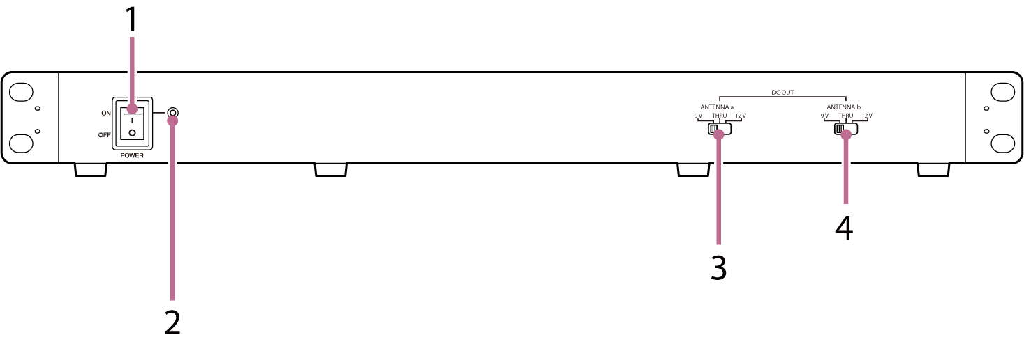
1. POWER switch
Press this switch to turn the unit ON/OFF.
2. Power indicator
Lit when the unit is turned ON.
3. ANTENNA a DC OUT (antenna a output voltage) selector switch
Switches the power supply to the antennas connected to the ANTENNA a IN/DC OUT1 and 2 connectors on the rear panel between 9 V/THRU/12 V.
4. ANTENNA b DC OUT (antenna b output voltage) selector switch
Switches the power supply to the antennas connected to the ANTENNA b IN/DC OUT1 and 2 connectors on the rear panel between 9 V/THRU/12 V.
ANTENNA a/b DC OUT selector switch power settings
| Powered device | Switch position |
|---|---|
| AN-57 | THRU |
| WB-01 | 9 V or 12 V |
| AN-820 | 9 V |
| AN-01 | 9 V or 12 V |
Note
- When connecting an AN-57 ground plane antenna, turn the DC power delivery setting to OFF in the UTILITY menu of the receiver.
TP1001803122