Rear Panel
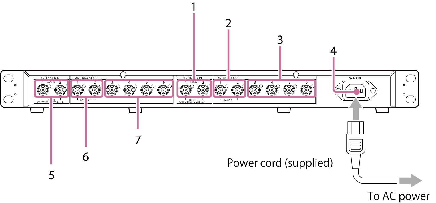
ANTENNA a block
1. ANTENNA a IN/DC OUT1, 2 (antenna a input/DC power outputs 1, 2) connectors
Inputs the signal from the antenna via a coaxial cable and simultaneously supplies power to the antenna side to drive the antenna booster. Use the ANTENNA a DC OUT switch on the front panel to switch between 9 V/THRU/12 V. You can connect up to two antennas according to the range of your wireless microphone.
2. ANTENNA a OUT1, 2 (CASCADE) (antenna a divider outputs 1, 2 (cascade dual use)) connectors
To use two dividers simultaneously, connect to the ANTENNA a IN/DC OUT1, 2 connectors of the second divider.
3. ANTENNA a OUT3 to 6 (antenna a divider outputs 3 to 6) connectors
Connect to the ANTENNA a IN connector on the receiver side. Connect such that ANTENNA a OUT connects to ANTENNA a IN.
Power supply block
4. AC IN (AC power input) connector
Connect to AC power cord.
ANTENNA b block
5. ANTENNA b IN/DC OUT1, 2 (antenna b input/DC power outputs 1, 2) connectors
Inputs the signal from the antenna via a coaxial cable and simultaneously supplies power to the antenna side to drive the antenna booster. Use the ANTENNA b DC OUT switch on the front panel to switch between 9 V/THRU/12 V. You can connect up to two antennas according to the range of your wireless microphone.
6. ANTENNA b OUT1, 2 (CASCADE) (antenna b divider outputs 1, 2 (cascade dual use)) connectors
To use two dividers simultaneously, connect to the ANTENNA b IN/DC OUT1, 2 connectors of the second divider.
7. ANTENNA b OUT3 to 6 (antenna b divider outputs 3 to 6) connectors
Connect to the ANTENNA b IN connector on the receiver side. Connect such that ANTENNA b OUT connects to ANTENNA b IN.