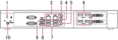
Names of Parts of the Main Unit
Front panel

-
Power switch
Supplies power to the main unit.
When power is turned on, the LED around the switch is lit green.
-
USB connectors (USB 2.0)
Use to connect to a mouse (sold separately) or USB flash drive (sold separately).
Rear panel
-
Security slot
Connect an anti-theft security lock cable.
-
LAN 1 and 2 connectors (RJ-45)
Connect to a network using LAN cables.
Note
- The use of the LAN 1 connector only is recommended.
If the LAN 2 connector is used at the same time, the protocol used by Vision Exchange must be transmitted and received by the correct NIC. To use LAN1 and LAN2 together, the network administrator must set the appropriate routing in the Windows settings. Failing to do so may cause unexpected trouble, such as problems with mirroring images. - The LAN 1 and LAN 2 connectors have the same function. There is no function to restrict external access, such as by web access, to either connector.
- There is no mutual communication between LAN 1 and LAN 2 by factory default.
- Do not set LAN 1 and LAN 2 to the same subnet.
- The use of the LAN 1 connector only is recommended.
-
LINE-IN (audio line input) connector (mini jack)
Connect to the audio output connector of an audio device.
-
LINE-OUT (audio line output) connector (mini jack)
Connect to the audio input connector of a speaker or other device.
Audio from an audio device connected to the LINE IN connector or audio from a user device can be output from a speaker.
-
MIC-IN (microphone input) connector (mini jack)
Note
- 2.5 V power is supplied to the microphone connected to the MIN-IN connector using plug-in power. Do not connect a microphone that does not support plug-in power directly to the connector.
-
HDMI IN (HDMI input) 1 to 4* connectors
Connect to the HDMI output connector of a camera, computer, or other video device.
* The PEQ-C100 has only two HDMI IN connectors.
-
USB connectors (USB 3.0)
Connect to an optional mouse, keyboard, touch panel, or camera, such as the SRG-120DU HD Color Video Camera.
-
HDMI OUT (HDMI output) connector
Connect to the HDMI input connector of a display, projector, or other video device to display the video from the main unit.
-
DISPLAY PORT (DisplayPort output) connector
Connect to the DisplayPort input connector of a display, projector, or other video device to display the video from the main unit.
-
19.5V (19.5 V DC power supply) jack
Connect to the supplied AC adapter.