Identifying the parts
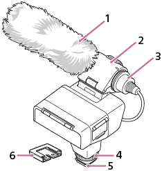
Body parts
-
Wind screen
-
Microphone holder
-
Microphone
-
Lock dial
-
Multi Interface foot
Note
- Do not touch the connector of the Multi Interface foot with bare hands.
-
Connector protect cap
Switches and dials
-
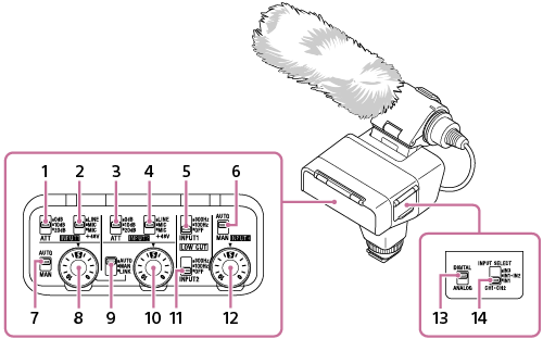
ATT (INPUT1) switch
Select the standard input level of the INPUT1 jack. This switch setting is active when the INPUT1 (LINE/MIC/MIC+48V) switch is set to “MIC” or “MIC+48V.”
-
INPUT1 (LINE/MIC/MIC+48V) switch
Select the option suitable for the device connected to the INPUT1 jack.
-
ATT (INPUT2) switch
Select the standard input level of the INPUT2 jack. This switch setting is active when the INPUT2 (LINE/MIC/MIC+48V) switch is set to “MIC” or “MIC+48V.”
-
INPUT2 (LINE/MIC/MIC+48V) switch
Select the option suitable for the device connected to the INPUT2 jack.
-
LOW CUT (INPUT1) switch
Use this switch to minimize unwanted noises by attenuating low-frequency components of the input audio from the INPUT1 jack.
-
AUTO/MAN (INPUT3) switch
Select the method (Auto/Manual) to adjust the volume level of the input audio from the INPUT3 jack.
-
AUTO/MAN (INPUT1) switch
Select the method (Auto/Manual) to adjust the volume level of the input audio from the INPUT1 jack.
-
AUDIO LEVEL (INPUT1) dial
Adjust the recording volume level of the input audio from the INPUT1 jack.
-
AUTO/MAN/LINK (INPUT2) switch
Select the method (Auto/Manual/Link to INPUT1) to adjust the volume level of the input audio from the INPUT2 jack.
-
AUDIO LEVEL (INPUT2) dial
Adjust the recording volume level of the input audio from the INPUT2 jack.
-
LOW CUT (INPUT2) switch
Use this switch to minimize unwanted noises by attenuating low-frequency components of the input audio from the INPUT2 jack.
-
AUDIO LEVEL (INPUT3) dial
Adjust the recording volume level of the input audio from the INPUT3 jack.
-
DIGITAL/ANALOG switch
Select the digital or analog input type.
If your camera is compatible with the digital audio interface of the Multi Interface Shoe, set the switch to “DIGITAL.”
This allows the unit and the attached camera to communicate with each other with digital signals and provide audio recording with minimum noise insertion.
-
INPUT SELECT switch
Select the audio input for recording audio to the channels on the attached camera.
Ports and jacks
-
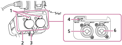
Release lever
-
Micro USB port
-
Cable holder
-
INPUT3 jack (Stereo mini-jack, plug-in-power compatible)
-
INPUT2 jack (3-pin XLR/TRS, female type, phantom-power compatible)
-
INPUT1 jack (3-pin XLR/TRS, female type, phantom-power compatible)