Locating parts and controls
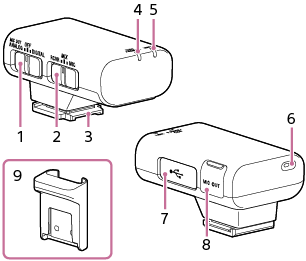
Receiver
-
Slide switch (MIC OUT ANALOG/Power OFF/DIGITAL)
Select “MIC OUT ANALOG” (analog audio output), “OFF” (power off), or “DIGITAL” (digital audio output).
If your camera is compatible with the digital audio interface of the Multi Interface Shoe, set the switch to “DIGITAL.”
This allows the receiver to pass the received audio to the camera with digital signals and provides audio recording with minimum noise insertion.
When you do not intend to use the receiver, select “OFF” with this switch to conserve the battery power.
-
Mode switch (RCVR/MIX/MIC)
Before you start recording with the camera, select a receiver mode with this switch to specify the microphone to use for recording.
-
Multi Interface foot
-
Power lamp (Green: Powered, Orange: Charging the battery)
Indicates the power state of the receiver or the battery charge state.
-
While the receiver is turned off, connecting the receiver to a computer with the supplied micro USB cable starts charging the receiver's built-in battery and turns on the power lamp in orange.
-
The orange blinking power lamp indicates that battery charging is needed.
-
-
LINK lamp
Indicates the connection state between the receiver and the microphone.
-
Internal microphone
-
Micro USB terminal
Connect the supplied micro USB cable to supply power to the receiver or charge the battery.
-
Microphone out jack
You can record audio by connecting the receiver to a camera with the supplied recording cable.
To use this jack, be sure to select “MIC OUT ANALOG” with the slide switch.
-
Connector protect holder
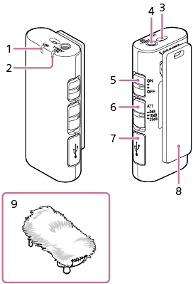
Microphone
-
LINK lamp
Indicates the connection state between the receiver and the microphone.
-
Power lamp (Green: Powered, Orange: Charging the battery)
Indicates the power state of the microphone or the battery charge state.
-
While the microphone is turned off, connecting the microphone to a computer with the supplied micro USB cable starts charging the microphone's built-in battery and turns on the power lamp in orange.
-
The orange blinking power lamp indicates that battery charging is needed.
-
-
Internal microphone
-
External microphone input jack
Connecting an external microphone (not supplied) to this jack automatically switches the audio input source to the connected external microphone.
-
Power switch
When you do not intend to use the microphone, select “OFF” with this switch to conserve the battery power.
-
ATT switch
Select the option suitable for the audio recording volume. To record loud sounds while minimizing distortion, select “20dB.” To record quiet sounds while amplifying the sounds, select “0dB.” “10dB” is the recommended volume level for recording human voices. It is advised that you determine and specify the level while monitoring the volume level meter on the camera.
-
Micro USB terminal
Connect the supplied micro USB cable to supply power to the microphone or charge the battery.
-
Clip
Use this clip for attaching the microphone to your clothing.
-
Wind screen
Attach the wind screen to the microphone to reduce pop noise caused by breath or strong wind.