Locating parts and controls
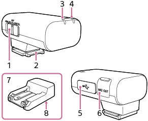
Receiver
-
Slide switch (ANALOG/OFF/DIGITAL)
Select “ANALOG” (analog audio output), “OFF” (power off), or “DIGITAL” (digital audio output).
-
If your camera is compatible with the digital audio interface of the Multi Interface Shoe, set the switch to “DIGITAL.”
Digital signal transmission from the receiver to the camera has the following merits over analog signal transmission that is enabled by the switch being set to “ANALOG.”
-
Audio recording with less noises
-
Less audio delay during recording
-
Recording with 24-bit audio (only available in combination with the compatible camera)
Note
- Movies recorded with 24-bit audio may not be played back normally on devices or software incompatible with 24-bit audio, resulting in unexpectedly loud volumes or no sound.
-
-
If your camera is not compatible with the digital audio interface of the Multi Interface Shoe, set the switch to “ANALOG.”
When the message “This accessory is not supported by the device and cannot be used.” is displayed on the camera, set the switch to “ANALOG.”
If this does not help, see here.
-
When a TRS audio cable with the 3.5 mm diameter plug (commercially available) is connected, the receiver outputs analog signals via the cable.
-
When a device with a USB audio input capability is connected, the receiver outputs digital signals.
-
When you do not intend to use the receiver, set the switch to “OFF” to conserve the battery power.
-
-
Multi Interface foot
-
Power lamp (Green: Powered, Orange: Charging the battery)
Indicates the power state of the receiver or the battery charge state.
When the power lamp stays blinking in orange, battery charging is needed.
-
LINK lamp
Indicates the connection state between the receiver and the microphone.
-
USB Type-C® port
Connect to a power source with a USB Type-C cable (commercially available) for charging the built-in battery of the receiver and/or for supplying power to the receiver.
This port can be connected to a device with a USB audio input capability, such as a computer or a smartphone, for audio recording as well.
-
Microphone out jack
Connect to the microphone in jack on the camera with a TRS audio cable with the 3.5 mm diameter plug (commercially available) for audio recording.
-
Connector Protect Holder/Stand
Attached to the receiver at the time of purchase.
-
Screw hole for tripod attachment (1/4 in. in diameter)
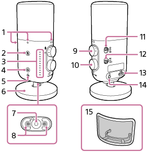
Microphone
-
Pop guard attachment mark
-
 (mute) button/lamp (Red: The microphone is in mute mode.)
 -
Indicator lamps
By default, level meter mode is indicated.
While the microphone is in level meter mode, briefly pressing the headphone volume/mixing ratio adjustment dial switches the mode to headphone volume adjustment mode.
While the microphone is in level meter mode, pressing and holding the headphone volume/mixing ratio adjustment dial for about 2 seconds switches the mode to mixing ratio adjustment mode.
To bring the microphone back into level meter mode, briefly press the headphone volume/mixing ratio adjustment dial or leave the microphone unused for 3 seconds or longer while the microphone is in headphone volume adjustment mode or in mixing ratio adjustment mode.
-
 (power) button/lamp (Green: Powered, Orange: Charging the battery)
Indicates the power state of the microphone or the battery charge state.
When the
(power) lamp stays blinking in orange, battery charging is needed. -
LINK lamp
Indicates the connection state between the receiver and the microphone.
-
Stand
Attached to the microphone at the time of purchase.
-
Screw hole for tripod attachment (1/4 inch in diameter)
-
Stand attachment hole
-
AUDIO LEVEL dial
Adjusts the recording volume level of the audio from the microphone.
Note
-
Turning the AUDIO LEVEL dial does not change the input level for the audio from the computer or smartphone via the USB connection.
-
-
Headphone volume/mixing ratio adjustment dial
Press this dial briefly to place the microphone into headphone volume adjustment mode; press and hold the dial for about 2 seconds to place the microphone into mixing ratio adjustment mode.
-
Directivity selection switch
 : Monaural, Uni-directional
You can record the sounds coming across from the front while minimizing those coming from the back. This directivity is suitable for recording the voice of a single person, for example, for making podcast or narrative recordings.
 : Monaural, Omni-directional
Sounds from all directions are equally picked. This directivity is suitable for recording the voices of multiple persons or for making recordings that capture the on-site atmosphere.
 : Stereo, Uni-directional
Widespread sounds are captured with a rich sense of realism. This directivity is suitable, for example, for music recording.
-
Filter switch (NC/LC/OFF)
NC: Select this option to use the noise cut filter function. Unpleasant noises are effectively eliminated by digital signal processing. If the sound quality does not seem appropriate, select “OFF.”
LC: Select this option to use the low cut filter function. Unwanted noises, such as wind noises, air-conditioning noises, and vibration noises, are minimized.
OFF: Select this option to disable either of the filter functions.
-
USB Type-C® port
Connect to a power source with a USB Type-C cable (commercially available) for charging the built-in battery of the microphone and/or for supplying power to the microphone.
This port can be connected directly to a device with a USB audio input capability, such as a computer or a smartphone, for audio recording as well.
-
Headphone out jack
Connect headphones (commercially available) for audio monitoring while the microphone is connected to a device, such as a computer or a smartphone, via the USB connection.
-
Pop guard
Attach the pop guard to the microphone.
Popping noises caused by breath are reduced when you speak close to the microphone.