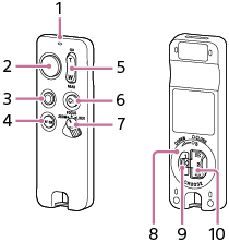
Identifying the parts (RMT-VP2)
-
Indicator
Indicates the camera's operational state in accordance with the remote commander operation. For details, see “Indicator activities.”
-
Shutter button
Releases the camera shutter. For details, see “Shooting a still image.”
-
MOVIE button
Starts recording a movie with the camera. For details, see “Shooting a movie.”
-
AF-ON button*
-
Zoom/Focus button
Zooms in/out the camera or adjusts the camera focus. Set the remote commander's ZOOM/FOCUS/LOCK switch to the “ZOOM” or “FOCUS” position suitable for your purpose. For details, see “Zooming the camera” or “Adjusting the camera focus.”
-
C1 button*
-
ZOOM/FOCUS/LOCK switch
When the switch is set to the “LOCK” position, the remote commander is disabled to prevent accidental operation of the camera.
To reduce battery consumption, it is recommended to set the switch to the “LOCK” position when this unit is not in use.
-
Battery cover
-
Battery cover locking latch
-
Battery cover turning knob
* Each of these buttons activates the function assigned to either the AF-ON button or the C1 button on the camera, if the camera has those buttons. For details about the camera's settings, refer to the Help Guide of your camera.
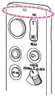
About the built-in Bluetooth antenna
The remote commander is equipped with a built-in Bluetooth antenna at the section shown in the following illustration. When you operate the remote commander, keep your hand away from the section to prevent a possible Bluetooth connection failure.