Locating parts and controls
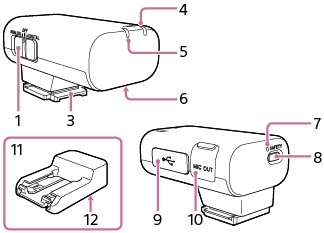
Receiver
ECM-W3
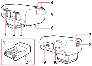
ECM-W3S
-
Slide switch (ANALOG/OFF/DIGITAL)
Select “ANALOG” (analog audio output), “OFF” (power off), or “DIGITAL” (digital audio output).
-
If your camera is compatible with the digital audio interface of the Multi Interface Shoe, set the switch to “DIGITAL.”
Digital signal transmission from the receiver to the camera has the following merits over analog signal transmission that is enabled by the switch being set to “ANALOG.”
-
Audio recording with less noises
-
Less audio delay during recording
-
Recording with 24-bit audio (only available in combination with the compatible camera)
Note
- Movies recorded with 24-bit audio may not be played back normally on devices or software incompatible with 24-bit audio, resulting in unexpectedly loud volumes or no sound.
-
-
If your camera is not compatible with the digital audio interface of the Multi Interface Shoe, set the switch to “ANALOG.”
When the message “This accessory is not supported by the device and cannot be used.” is displayed on the camera, set the switch to “ANALOG.”
If this does not help, see here.
-
When a TRS audio cable with the 3.5 mm diameter plug (commercially available) is connected, the receiver outputs analog signals via the cable.
-
When a device with a USB audio input capability is connected, the receiver outputs digital signals.
-
When you do not intend to use the receiver, set the switch to “OFF” to conserve the battery power.
-
-
Mode switch (SEP/MIX) (ECM-W3)
By selecting a receiver mode with this switch before you start video recording with the camera, you can make recordings with audio from either of the two microphones individually as the left or right channel audio; or recordings with mixed audio from the two microphones.
-
Multi Interface foot
-
LINK (LINK1/LINK2) lamp (ECM-W3)
LINK lamp (ECM-W3S)
Indicates the connection state between the receiver and the microphone.
Hint
-
On the nameplate under the clip of the microphone, you will find either the number “1” or “2” indicated for microphone identification. The number “1” indicates the microphone No. 1; and the number “2” indicates the microphone No. 2. To identify which microphone connection is active with the receiver, check the state of the LINK1 lamp for the microphone No. 1 and the LINK2 lamp for the microphone No. 2 on the receiver. (Applicable to ECM-W3)
-
-
Power lamp (Green: Powered, Orange: Charging the battery)
Indicates the power state of the receiver or the battery charge state.
When the power lamp stays blinking in orange, battery charging is needed.
-
Charging connector
Supplies power to the receiver for battery charging via the charging case.
-
SAFETY lamp
Lights in yellow when the receiver goes into SAFETY mode and goes out when the receiver comes out of the mode.
-
SAFETY button
Pressing and holding the SAFETY button for about 2 seconds places the receiver into SAFETY mode.
For details, see About the SAFETY button.
-
USB Type-C® port
Connect to a power source with a USB Type-C cable (commercially available) for charging the built-in battery of the receiver and/or for supplying power to the receiver.
This port can be connected to a device with a USB audio input capability, such as a computer or a smartphone, for audio recording as well.
-
Microphone out jack
Connect to the microphone in jack on the camera with a TRS audio cable with the 3.5 mm diameter plug (commercially available) for audio recording.
-
Connector Protect Holder/Stand
Attached to the receiver at the time of purchase.
-
Screw hole for tripod attachment (1/4 in. in diameter)
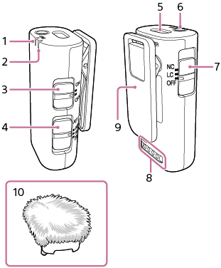
Microphone
-
LINK lamp
Indicates the connection state between the receiver and the microphone.
Hint
-
On the nameplate under the clip of the microphone, you will find either the number “1” or “2” indicated for microphone identification. The number “1” indicates the microphone No. 1; and the number “2” indicates the microphone No. 2. To identify which microphone connection is active with the receiver, check the state of the LINK1 lamp for the microphone No. 1 and the LINK2 lamp for the microphone No. 2 on the receiver. (Applicable to ECM-W3)
-
-
Power lamp (Green: Powered, Orange: Charging the battery)
Indicates the power state of the microphone or the battery charge state.
When the power lamp stays blinking in orange, battery charging is needed.
-
Power switch
When you do not intend to use the microphone, select “OFF” with this switch to conserve the battery power.
-
ATT switch
Select the option suitable for the audio recording volume. To record loud sounds while minimizing distortion, select “20dB.” To record quiet sounds, select “0dB.” “10dB” is the recommended volume level for recording human voices. It is recommended that you select an option while monitoring the volume level meter on the camera or the audio recording volume with headphones.
-
Internal microphone
-
External microphone input jack (monaural)
Connecting an external microphone (not supplied) to this jack automatically switches the audio input source to the connected external microphone.
-
Filter switch (NC/LC/OFF)
NC: Select this option to use the noise cut filter function. Unpleasant noises are effectively eliminated by digital signal processing. If the sound quality does not seem appropriate, select “OFF.”
LC: Select this option to use the low cut filter function. Unwanted noises, such as wind noises, air-conditioning noises, and vibration noises, are minimized.
OFF: Select this option to disable either of the filter functions.
-
Charging connector
Supplies power to the microphone for battery charging via the charging case.
-
Clip
Use this clip for attaching the microphone to your clothing.
-
Wind screen
Attach the wind screen to the microphone to reduce noises caused by breath or strong wind.
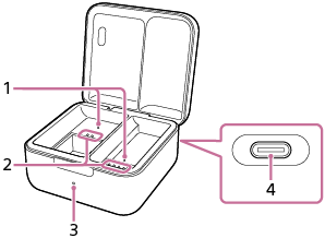
Charging case
ECM-W3
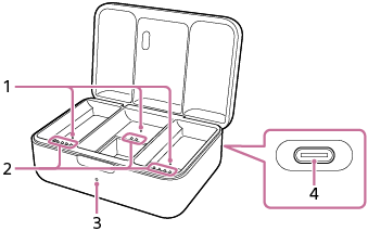
ECM-W3S
-
Detection pin
Detects when the receiver and the microphone are both housed in the charging case.
-
Charging connector
-
Charging lamp
Indicates the battery charging state of the charging case.
-
USB Type-C® port
Connect to a power source with a USB Type-C cable (commercially available) for charging the built-in batteries of the charging case as well as of the receiver and the microphone housed in the case.
Note
- To prevent a malfunction, do not deliberately push in the detection pin and/or any of the charging connectors unless you intend to place the receiver and the microphone in the charging case.