Identifying the parts
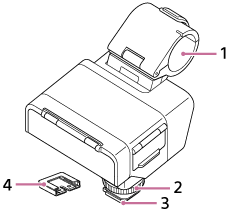
Body parts
-
Microphone holder
-
Lock dial
-
Multi Interface foot
Note
- Do not touch the connector of the Multi Interface foot with bare hands.
-
Connector protect cap
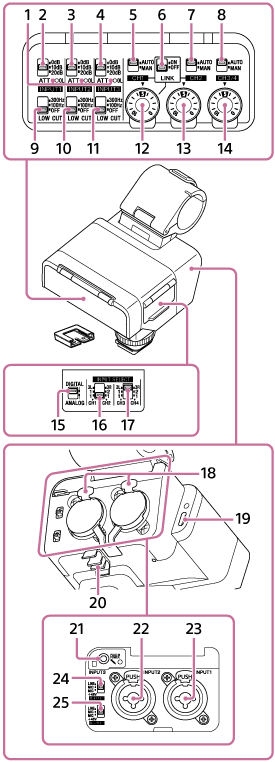
Switches/dials/jacks
-
OL (overload) lamps
Light up when the input audio signal is large enough to cause analog clipping. In such cases, adjust the input level using the connected device or the ATT switch on this unit so that the lamp does not light up during operation.
-
ATT (INPUT1) switch
Select the standard input level of the INPUT1 jack. This switch setting is active when the INPUT1 (LINE/MIC/MIC+48V) switch is set to “MIC” or “MIC+48V.”
-
ATT (INPUT2) switch
Select the standard input level of the INPUT2 jack. This switch setting is active when the INPUT2 (LINE/MIC/MIC+48V) switch is set to “MIC” or “MIC+48V.”
-
ATT (INPUT3) switch
Select the standard input level of the INPUT3 jack.
-
AUTO/MAN (CH1) switch
Select the method (Auto/Manual) to adjust the volume level of the output audio to the CH1 on the camera or computer.
-
LINK switch
Setting the switch to “ON” allows the recording volume level of the audio output to CH2 on the camera or computer to automatically follow that of CH1. This is useful when recording in stereo to CH1 and CH2.
-
AUTO/MAN (CH2) switch
Select the method (Auto/Manual) to adjust the volume level of the output audio to the CH2 on the camera or computer.
-
AUTO/MAN (CH3/4) switch
Select the method (Auto/Manual) to adjust the volume level of the output audio to the CH3 and CH4 on the camera.
-
LOW CUT (INPUT1) switch
Use this switch to minimize unwanted noises by attenuating low-frequency components of the input audio from the INPUT1 jack. This switch setting is active when the INPUT1 (LINE/MIC/MIC+48V) switch is set to “MIC” or “MIC+48V.”
-
LOW CUT (INPUT2) switch
Use this switch to minimize unwanted noises by attenuating low-frequency components of the input audio from the INPUT2 jack. This switch setting is active when the INPUT2 (LINE/MIC/MIC+48V) switch is set to “MIC” or “MIC+48V.”
-
LOW CUT (INPUT3) switch
Use this switch to minimize unwanted noises by attenuating low-frequency components of the input audio from the INPUT3 jack.
-
AUDIO LEVEL (CH1) dial
Adjust the recording volume level of the output audio to the CH1 on the camera or computer.
-
AUDIO LEVEL (CH2) dial
Adjust the recording volume level of the output audio to the CH2 on the camera or computer.
-
AUDIO LEVEL (CH3/4) dial
Adjust the recording volume level of the output audio to the CH3 and CH4 on the camera.
-
DIGITAL/ANALOG switch
Select the output type, digital or analog.
If the Multi Interface Shoe on your camera is not compatible with the digital audio interface, set the switch to “ANALOG.”
-
INPUT SELECT (CH1/CH2) switch
Select the input audio to output to the CH1 and CH2 on the camera or computer.
-
INPUT SELECT (CH3/CH4) switch
Select the input audio to output to the CH3 and CH4 on the camera.
-
Release lever
-
USB Type-C® port
Note
-
The USB Type-C port on this unit is for connecting to a computer that supports USB audio input. As this port does not support power input from USB power supplies (including USB PD), the unit will not be powered even if connected to them.
-
-
Cable holder
-
INPUT3 jack (Stereo mini-jack, plug-in-power compatible)
-
INPUT2 jack (3-pin XLR/TRS*, female type, +48 V phantom-power compatible)
* 3-pole jack (TIP: HOT, RING: COLD, SLEEVE: GND)
-
INPUT1 jack (3-pin XLR/TRS*, female type, +48 V phantom-power compatible)
* 3-pole jack (TIP: HOT, RING: COLD, SLEEVE: GND)
-
INPUT2 (LINE/MIC/MIC+48V) switch
Select the option suitable for the device connected to the INPUT2 jack.
-
INPUT1 (LINE/MIC/MIC+48V) switch
Select the option suitable for the device connected to the INPUT1 jack.