Names of Parts of the Main Unit
Front panel

-
Power switch
Supplies power to the main unit.
When power is turned on, the LED around the switch is lit green.
-
USB connectors (USB 2.0)
Use to connect to a mouse (sold separately) or USB flash drive (sold separately).
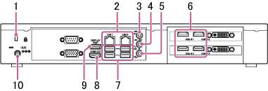
Rear panel
-
Security slot
Connect an anti-theft security lock cable.
-
LAN 1 and 2 connectors (RJ-45)
Connect to a network using LAN cables.
Note
- Basically, use the LAN 1 connector. The LAN 2 connector should not be used.
- If the LAN 2 connector must be used, technical knowledge of the network settings of Vision Exchange and Windows OS is required.
For details, consult the system administrator. - The LAN 1 and LAN 2 connectors have the same function. There is no function to restrict external access, such as by web access, to either connector.
- There is no mutual communication between LAN 1 and LAN 2 by factory default.
- Do not set LAN 1 and LAN 2 to the same subnet.
-
LINE-IN (audio line input) connector (mini jack)
Connect to the audio output connector of an audio device.
-
LINE-OUT (audio line output) connector (mini jack)
Connect to the audio input connector of a speaker or other device.
Audio from an audio device connected to the LINE IN connector or audio from a user device can be output from a speaker.
-
MIC-IN (microphone input) connector (mini jack)
Note
- 2.5 V power is supplied to the microphone connected to the MIN-IN connector using plug-in power. Do not connect a microphone that does not support plug-in power directly to the connector.
-
HDMI IN (HDMI input) 1 to 4* connectors
Connect to the HDMI output connector of a camera, computer, or other video device.
* The PEQ-C100 has only two HDMI IN connectors.
-
USB connectors (USB 3.0)
Connect to an optional mouse, keyboard, touch panel, or camera, such as the SRG-120DU HD Color Video Camera.
-
HDMI OUT (HDMI output) connector
Connect to the HDMI input connector of a display, projector, or other video device to display the video from the main unit.
-
DISPLAY PORT (DisplayPort output) connector
Connect to the DisplayPort input connector of a display, projector, or other video device to display the video from the main unit.
-
19.5V (19.5 V DC power supply) jack
Connect to the supplied AC adapter.