Identifying parts
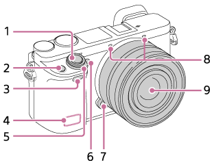
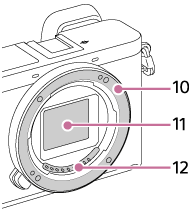
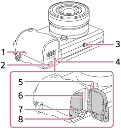
When the lens is removed
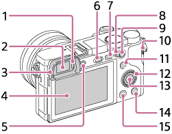
- Shutter button
- C1 (Custom 1) button
- Infrared remote sensor
- Wi-Fi/Bluetooth antenna (built-in)
- ON/OFF (Power) switch
- Self-timer lamp/AF illuminator
- Lens release button
- Microphone*
- Lens
- Mount
- Image sensor**
- Lens contacts**
* Do not cover this part during movie recording. Doing so may cause noise or lower the volume.
** Do not directly touch these parts.
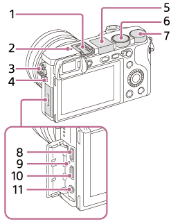
- Multi Interface Shoe*
-
 Image sensor position mark
- The image sensor is the sensor that converts light into an electric signal. The mark shows the location of the image sensor. When you measure the exact distance between the camera and the subject, refer to the position of the horizontal line.
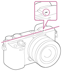
- If the subject is closer than the minimum shooting distance of the lens, the focus cannot be confirmed. Make sure you put enough distance between the subject and the camera.
- The image sensor is the sensor that converts light into an electric signal. The
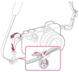
- Hooks for shoulder strap
Attach both ends of the strap onto the camera.
- Speaker
- Flash
- Press the
 (Flash pop-up) button to use the flash. The flash
does not pop up automatically.
(Flash pop-up) button to use the flash. The flash
does not pop up automatically. - When not using the flash, press it back into the camera body.
- Press the
- Mode dial
- Control dial
- Multi/Micro USB Terminal*
This terminal supports Micro USB-compatible devices.
- Charge lamp
- HDMI micro jack
-
 (Microphone) jack
When an external microphone is connected, the built-in microphone turns off automatically. When the external microphone is a plugin-power type, the power of the microphone is supplied by the camera.
* For details on compatible accessories for the multi interface shoe and the Multi/Micro USB Terminal, visit the Sony website, or consult your Sony dealer or local authorized Sony service facility. Accessories for the Accessory Shoe can also be used. Operations with other manufactures’ accessories are not guaranteed.


- Eye sensor
- Viewfinder
- Eyepiece Cup
- Not attached to the camera at the factory. It is recommended that you attach the eyepiece cup when you intend to use the viewfinder.
Match the eyepiece cup to the groove on the viewfinder and slide it into place.
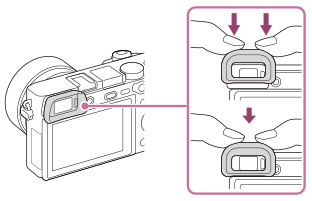
To remove the eyepiece cup, grasp it on the left and right sides and lift it up.
- Remove the eyepiece cup when you attach an accessory (sold separately) to the Multi Interface Shoe.
- Monitor
- You can change the monitor angle to shoot from any position you like.
High position (holding the camera high)
Low position (holding the camera low)
Selfie position (facing the monitor toward you to take a selfie)
- You may not be able to adjust the monitor angle depending on the type of a tripod you use. In such a case, release the tripod screw once to adjust the monitor angle.
- You can change the monitor angle to shoot from any position you like.
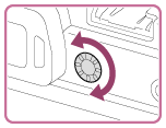
- Diopter-adjustment dial
- Adjust the diopter-adjustment dial to your eyesight until the display appears clearly in the viewfinder. If it is difficult to turn the diopter-adjustment dial, remove the eyepiece cup and then adjust the dial.
- Adjust the diopter-adjustment dial to your eyesight until the display appears clearly in the viewfinder. If it is difficult to turn the diopter-adjustment dial, remove the eyepiece cup and then adjust the dial.
-
(Flash pop-up) button
- MENU button
- AF/MF/AEL switch lever
- For shooting: AF/MF button/AEL button
For viewing: (Enlarge) button
 - MOVIE (Movie) button
- For shooting: Fn (Function) button
For viewing: (Send to Smartphone) button
You can display the screen for [Send to Smartphone] by pressing this button.
- Control wheel
- Center button
-
C2 (Custom 2) button/
 (Delete) button
 -
 (Playback) button
-
 (N mark)
- Touch the mark when you connect the camera to a smartphone equipped with the NFC function. For details on the location of the (N mark) on your Smartphone, refer to the operating instructions of the Smartphone.
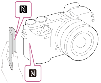
- NFC (Near Field Communication) is an international standard of the short-range wireless communication technology.
- Touch the mark when you connect the camera to a smartphone equipped with the NFC function. For details on the location of the
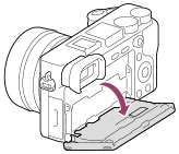
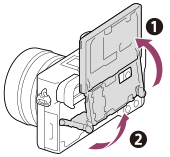
- Connection plate cover
- Use this when using an AC-PW20 AC Adaptor (sold separately). Insert the connection plate into the battery compartment, and then pass the cord through the connection plate cover as shown below.
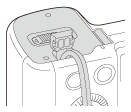
- Make sure that the cord is not pinched when you close the cover.
- Use this when using an AC-PW20 AC Adaptor (sold separately). Insert the connection plate into the battery compartment, and then pass the cord through the connection plate cover as shown below.
- Tripod socket hole
Use a tripod with a screw less than 5.5 mm (7/32 inches) long. Otherwise, you cannot firmly secure the camera, and damage to the camera may occur.
- Access lamp
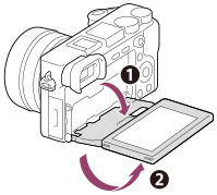
- Battery/memory card cover
- Memory card slot
- Battery insertion slot
- Battery lock lever