Rear Side/Connector Block/Card Slots
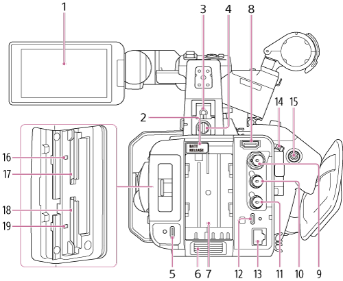
- LCD monitor/Touch panel
-
BATT RELEASE (battery release) button
Press the button to remove the battery.
-
Multi interface shoe

For details about accessories supported by the multi interface shoe, contact your sales representative.
-
Accessory shoe fall prevention wire screw
Note
- Also turn the accessory locking knob toward the “LOCK” arrow side to secure it in place.
-
USB-C® power supply input connector
Dedicated power supply input USB Type-C connector. Does not support data communication or power supply output.
The screw hole on the left side of the USB-C connector is for a screw lock Type-C cable.
-
Air inlet
Note
- Do not cover the air inlet.
- Battery compartment
-
HDMI output connector
Outputs an HDMI signal.
-
SDI OUT connector (BNC type)
Outputs an SDI signal.
-
TC IN/OUT connector (BNC type)
Timecode input/output connector.
Used for the following applications, depending on the REF/TC IN/OUT switch setting.
IN: Reference timecode signal input when locking the timecode of the unit to an external device.
OUT: Timecode signal output from the unit when locking the timecode of an external device to the timecode of the unit.
Note
- Connect a device that complies with the SMPTE digital standard to the TC IN/OUT connector. Connecting a non-compliant device (for example, devices that apply voltages outside the range of 0.5 V to 4.5 V) may damage the unit.
-
GENLOCK IN/REF OUT connector
GENLOCK IN/REF OUT input/output connector. Used for the following applications, depending on the REF/TC IN/OUT switch setting.
- GENLOCK IN: Reference signal input connector when using genlock from an external device or when locking the timecode of the unit to an external device.
- REF OUT: Reference signal (HD-Sync) output connector for synchronizing with an external device.
-
USB-C® data communication connector
USB Type-C connector. Supports data communication. The screw hole on the right side of the USB-C connector is for a screw lock Type-C cable.
-
LAN connector
Wired LAN connector.
-
Record START/STOP button / HOLD switch (grip)
Press the record START/STOP button, turning the light on, to start recording. Press again, turning the light off, to stop recording.
When the HOLD switch is in the HOLD position, the record START/STOP button cannot be pressed.
-
Multi selector
Used for auto focus operation and menu operation. Moves the cursor in 8 directions and selects values when pressed.
- Access indicator A
- CFexpress Type A/SD card slot (A)
- CFexpress Type A/SD card slot (B)
- Access indicator B