XLR handle unit (ILME-FX30 only)
Body parts
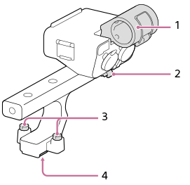
- Microphone holder
- Cable holder
- Attachment screws
- Multi Interface foot
Switches and dials
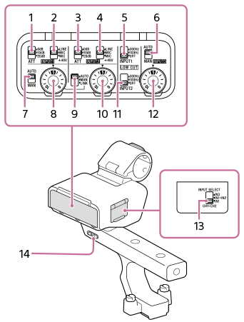
- ATT (INPUT1) switch
Select the standard input level of the INPUT1 jack. This switch setting is active when the INPUT1 (LINE/MIC/MIC+48V) switch is set to “MIC” or “MIC+48V.”
- INPUT1 (LINE/MIC/MIC+48V) switch
Select the option suitable for the device connected to the INPUT1 jack.
- ATT (INPUT2) switch
Select the standard input level of the INPUT2 jack. This switch setting is active when the INPUT2 (LINE/MIC/MIC+48V) switch is set to “MIC” or “MIC+48V.”
- INPUT2 (LINE/MIC/MIC+48V) switch
Select the option suitable for the device connected to the INPUT2 jack.
- LOW CUT (INPUT1) switch
Use this switch to minimize unwanted noise by attenuating low-frequency components of the input audio from the INPUT1 jack.
- AUTO/MAN (INPUT3) switch
Select the method (Auto/Manual) for adjusting the volume level of the input audio from the INPUT3 jack.
- AUTO/MAN (INPUT1) switch
Select the method (Auto/Manual) for adjusting the volume level of the input audio from the INPUT1 jack.
- AUDIO LEVEL (INPUT1) dial
Adjust the recording volume level of the input audio from the INPUT1 jack.
- AUTO/MAN/LINK (INPUT2) switch
Select the method (Auto/Manual/Link to INPUT1) for adjusting the volume level of the input audio from the INPUT2 jack.
- AUDIO LEVEL (INPUT2) dial
Adjust the recording volume level of the input audio from the INPUT2 jack.
- LOW CUT (INPUT2) switch
Use this switch to minimize unwanted noise by attenuating low-frequency components of the input audio from the INPUT2 jack.
- AUDIO LEVEL (INPUT3) dial
Adjust the recording volume level of the input audio from the INPUT3 jack.
- INPUT SELECT switch
Select the audio input for recording audio to the channels on the attached camera.
- HANDLE AUDIO switch
Enable audio input from the XLR adaptor.
Ports and jacks
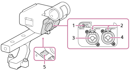
- INPUT3 jack (stereo mini-jack, plug-in-power compatible)
- Release lever
- INPUT2 jack (3-pin XLR/TRS, female type, phantom-power compatible)
- INPUT1 jack (3-pin XLR/TRS, female type, phantom-power compatible)
- Micro USB port
Note
- Do not touch the connectors with bare hands.