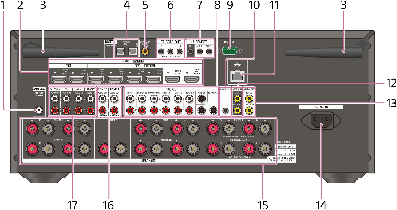
Rear panel (STR-AZ7000ES)
-
FM ANTENNA terminal
- HDMI IN/OUT jacks
Connect HDMI devices. For supported video signals, see “Connecting devices with HDMI jacks.”
-
Wireless LAN antenna
-
DIGITAL OPTICAL IN jacks
-
COAXIAL IN (SA-CD/CD) jack
- TRIGGER OUT jacks
Connect to interlock on/off of the power supply of other 12V TRIGGER compliant equipment, or the amplifier/receiver of Zone 2 or Zone 3.
-
IR REMOTE IN/OUT jacks
- You can control the receiver from a distance by connecting an IR repeater (not supplied) to the IR REMOTE IN jack.
- You can start or stop playback of devices such as a CD player connected to the receiver by connecting an IR blaster (not supplied) to the IR REMOTE OUT jack.
- PRE OUT jacks
Connect to an external power amplifier and a subwoofer.
-
RS232C port (*1)
- S-CENTER OUT jack
When the receiver is connected to the S-CENTER SPEAKER IN jack of your TV, you can output the center part of the receiver sound from the TV speakers. By using this connection, TV audio such as dialogue can be made to sound as if it is coming out of the TV screen. (Acoustic Center Sync function)
-
LAN port
-
VIDEO IN jacks
-
VIDEO OUT jacks
- AC IN terminal
Connect the supplied AC power cord (mains lead).
- SPEAKERS terminals
Connect to speakers.
- By changing the setting, HEIGHT 3 terminals can be used for the front wide, Zone 2 or center 2 speaker connection.
- With the center 2 speaker connection, by installing two speakers above and below the TV screen, for example, TV audio such as dialogue can be made to sound as if it is coming out of the TV screen. (Dual Center Speaker function)
-
ZONE 2/ZONE 3 AUDIO OUT (VARIABLE) jacks
-
AUDIO IN jacks
*1 This is the control expansion terminals for custom installation.