Sides
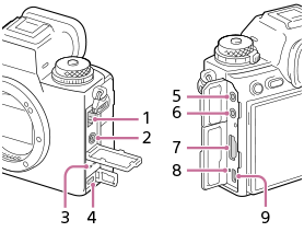
- LAN terminal
-
 (Flash sync) terminal
 - Speaker
- Multi/Micro USB Terminal*
This terminal supports Micro USB-compatible devices.
-
 (Microphone) jack
When an external microphone is connected, the built-in microphone turns off automatically. When the external microphone is a plugin-power type, the power of the microphone is supplied by the camera.
-
 (Headphones) jack
 - HDMI type A jack
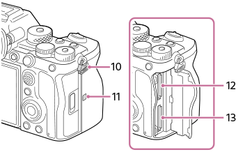
- Charge lamp
- USB Type-C terminal
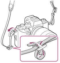
- Hooks for shoulder strap
Attach both ends of the strap onto the camera.
-
 (N-Mark)
- This mark indicates the touch point for connecting the camera and an NFC-enabled Smartphone.
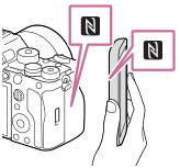
- NFC (Near Field Communication) is an international standard of short-range wireless communication technology.
- This mark indicates the touch point for connecting the camera and an NFC-enabled Smartphone.
- SLOT 1 (Memory card slot 1)
- SLOT 2 (Memory card slot 2)
* For details on compatible accessories for the Multi/Micro USB Terminal, visit the Sony website, or consult your Sony dealer or local authorized Sony service facility.
Notes on USB terminals
You can use either the USB Type-C terminal or the Multi/Micro USB Terminal for USB communications. However, you cannot conduct USB communications with both terminals simultaneously. Use the USB Type-C terminal to supply power and charge the battery pack. This camera cannot be powered via the Multi/Micro USB terminal.
- You can use accessories for the Multi/Micro USB Terminal, such as a remote commander (sold separately), while supplying power or performing PC Remote shooting using the USB Type-C terminal.
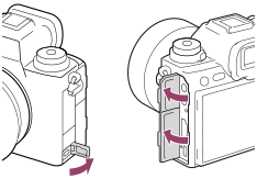
Notes on the terminal cover
Ensure that the terminal cover is closed before use.
Notes on the cable protector
Use the cable protector to prevent a cable from being disconnected when shooting images with the cable connected.
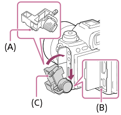
To attach the cable protector
- Open the headphone terminal cover, HDMI terminal cover, and Multi/Micro USB terminal cover.
- Fit the hook (A) of the cable protector into the notch (B) below the USB Type-C terminal, and attach it so that it covers the terminal surface of the camera while pressing down to keep it from coming off.
- Push the attachment screw (C) in and turn it to secure the cable protector.
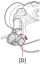
- Insert the cable into one of the jacks.
- Insert the cable into the holding part and then secure the cable with the fixing dial (D).
To remove the cable protector
Loosen the attachment screw, and then remove the cable protector.