Connecting to the Unit using a Remote Controller (Option) via RS-422
This topic describes how to connect a remote controller to the unit using the RS-422 connector. An RS-422 connection supports connections of up to 1.2 km (max).
You can also daisy-chain up to seven cameras using the VISCA OUT connector.
To configure the initial settings of the unit, a PC or tablet must be connected to the LAN connector.
Note
- Perform the following procedure before connecting the power supply to the unit.
-
Set SETUP switch 4 to the ON position on the connector block of the unit.
VISCA communication is enabled.

-
Set the baud rate using SETUP switch 5 on the connector block of the unit to the same baud rate as the remote controller.
Switch 5 setting Baud rate ON 38400 bps OFF 9600 bps -
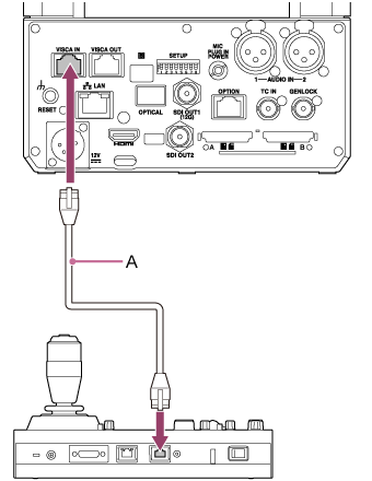
Connect the VISCA IN connector of the unit to the VISCA connector of the remote controller using a commercially available network cable.
The following shows an RM-IP500 connection example.

A: Commercially available network cable
Note
- Use a straight cable for the network cable.
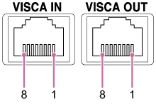
- To connect a VISCA device other than the RM-IP500 that has unique connector wiring, create a connection cable by referring to the pin layout shown below.
VISCA RS-422 pin layout (left: VISCA IN, right: VISCA OUT)

IN OUT Pin No. Function Pin No. Function 1 TX− 1 RX− 2 TX+ 2 RX+ 3 RX− 3 TX− 4 GND 4 GND 5 GND 5 GND 6 RX+ 6 TX+ 7 N.C. 7 N.C. 8 N.C. 8 N.C. Refer to the following when connecting multiple cameras in a daisy-chain.

A: Commercially available network cable
-
Turn the unit on.
TP1001804473

