Connector Block
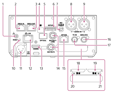
This topic describes the location and function of parts on the connector block of the unit.

-
 (ground) connection
Connect to ground by connecting to the ground terminal of a power outlet or to a grounding bar.
-
VISCA IN connector
Connect to a remote controller (option).
When connecting multiple cameras, connect to the VISCA RS-422 OUT connector of the previous camera.
-
VISCA OUT connector
When connecting multiple cameras, connect to the VISCA RS-422 IN connector of the next camera.
-
 Infrared remote control sensor (rear)
Infrared sensor for the supplied infrared remote control.
-
OPTICAL output connector
Outputs an SDI OUT1 (12G) connector signal converted to optical format when an SFP+ module (option) is connected.
- For details, see “Outputting an Optical Fiber Signal.”
-
SETUP switches

Configures the following settings.
Switch 1, 2: Selects the infrared remote control (supplied) that will perform operations.
Switch 1 setting Switch 2 setting Description OFF (default) OFF (default) Receives operations from the infrared remote control (supplied) with remote control ID of 1.
Default setting.OFF ON Receives operations from the infrared remote control (supplied) with remote control ID of 2. ON OFF Receives operations from the infrared remote control (supplied) with remote control ID of 3. ON ON Reserved Switch 3: Sets which settings are reset when the RESET switch is pressed.
Setting Description OFF (default) Resets the network connection settings only. The network settings, security settings, and user information (user name and password) of the unit will be reset. ON Resets all settings to factory defaults. Switch 4: Enables/disables VISCA and VISCA over IP communication. The settings are applied when the camera is turned on.
Set to the ON position to use the unit when connected to an RM-IP500 remote controller.
Setting Description OFF (default) Will not respond to VISCA commands. ON Accepts VISCA commands. Note
- If the administrator password has not been configured, VISCA communication is disabled, regardless of the switch setting. For details about configuring the administrator password, see “Initializing the Unit.”
Switch 5: Sets the VISCA IN/VISCA OUT connector baud rate. The settings are applied when the camera is turned on.
Setting Description OFF (default) Sets the baud rate to 9600 bps. ON Sets the baud rate to 38400 bps. Switch 6, 7: Reserved. Not used.
Switch 8: Sets the IP address to a specific value.
Setting Description OFF (default) The user sets the IP address. ON Sets the IP address of the unit to 192.168.0.100 at startup (fixed IP address mode). Note
- If the IP address is changed after startup in the web menu, set this switch to the OFF position.
-
MIC connector (stereo ø3.5 mm)
Connect to a ø3.5 mm stereo mini jack (3-pole) microphone.
-
AUDIO IN 1 connector (XLR type 3-pin connector)
-
AUDIO IN 2 connector (XLR type 3-pin connector)
Use to input the signal from an external microphone or audio device.
- For details, see “Connecting an External Microphone or External Audio Device.”
-
RESET switch
Press for at least 5 seconds using the tip of a pen or similar device to reset the settings of the unit to the factory default values.
You can select whether to reset the network connection settings only or all settings using SETUP switch 3.
-
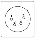
DC IN connector (XLR type 4-pin connector)
DC IN (DC power input) connector (XLR 4-pin, male) for connecting an external power supply to the unit. Supports an input voltage of 12 V DC (11 V to 17 V).

No. Signal 1 GND 2 NC 3 NC 4 DC IN (11 V to 17 V) Note
- If the power cable is extended to a long distance, a voltage drop will occur due to the load. Check that the input voltage at the power connector does not fall below 12 V before operating the unit.
- The unit monitors the voltage. If it falls below 11.5 V, [Voltage Low] is detected and a warning is displayed using the Web App, recording/tally lamp, and POWER lamp/NETWORK lamp.
- If it falls below 11.0 V, [Insufficient Voltage] is detected, various functions are stopped, and a warning is displayed using the Web App, recording/tally lamp, and POWER lamp/NETWORK lamp. When [Insufficient Voltage] is detected, the unit will not return to normal operating state if the voltage subsequently rises. Make sure that the power supply is stable, then disconnect the power cable and connect the power supply again.
-
 LAN (network) connector (RJ-45)
Connect a network cable (category 5e or higher) for network communication and PoE++* power supply to the unit.
*PoE++: Power over Ethernet Plus Plus. Conforms to IEEE802.3bt (Type 4 Class 8). For details about connecting, refer to the operating instructions for the power supply device.
Note
- Some functions are restricted during PoE++ operation. For details, see “Using PoE++ Power.”

A: Speed LED status indication
Display Connection speed Not lit 10 Mbps connection 100 Mbps connection Lit orange 1000 Mbps connection B: Link/ACT LED status indication
Display Connection status Not lit No link Blinking green Link established, data active Lit green Active link Note
- When connecting this product to the Internet, connect via a system that provides a protection function, such as a router or firewall. If connected without such protection, security issues may occur.
-
HDMI connector
Outputs the video from the unit as an HDMI signal.
- For details, see “HDMI OUT connector (Type A connector)” in “Connecting External Monitors and Recording Devices.”
-
SDI OUT 1 (12G) connector / SDI OUT 2 connector
SDI OUT 1 (12G) connector: Outputs the video from the unit as a 12G/6G/3G/1.5G SDI signal.
SDI OUT 2 connector: Outputs the video from the unit as a 3G/1.5G SDI signal.
- For details, see “SDI OUT connector (BNC type)” in “Connecting External Monitors and Recording Devices.”
-
OPTION connector
Use to connect a tally signal from an external device.
- For details, see “Connecting a Tally Signal.”
-
GENLOCK connector
Use to input an external sync signal.
- For details, see “Synchronizing the Phase of the Video Signal (Genlock).”
-
TC IN connector
Input an external reference timecode signal.
- For details, see “Locking the Timecode to Other Devices.”
-
CFexpress Type A / SD card slot (A)
-
CFexpress Type A / SD card slot (B)
Use for inserting recording media.
- For details, see “Inserting Memory Cards.”
-
Access indicator A
-
Access indicator B
Indicator is lit or blinks when recording media is inserted.
- For details, see “Inserting Memory Cards.”

