Parts and controls (Gimbal GBL-T3 (sold separately))
The locations of the parts and controls of the gimbal GBL-T3 (sold separately) are shown below.
-
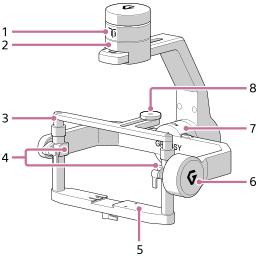
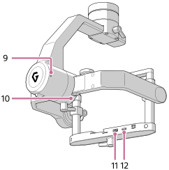
Pan motor
-
Pan adjustment
-
Tilt top bar
-
Tilt vertical adjustment
-
Tilt front-back adjustment
-
Tilt motor
-
Roll motor
-
Top camera screw
-
Status LED
LED color LED indication Status of the gimbal Red Lit up An error has occurred in the motor or IMU (*1). White Blinking Under calibration White Lit up Starting the motor or IMU. Yellow Blinking The motor or IMU is in a standby state. Blue Blinking The gimbal is starting up, so it cannot accept remote operations. Purple Blinking Being operated remotely *1 IMU: Inertial Measurement Unit
-
Roll adjustment
-
AUX port
-
USB port