


XLR handle unit (ILME-FX5 only)
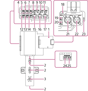
-
Microphone holder
-
Accessory attachment screw holes
Compatible with 1/4-20 UNC screws (length of 8.0 mm or shorter).
-
Accessory shoe mount/Accessory attachment screw hole
Compatible with 1/4-20 UNC screws (length of 7.5 mm or shorter).
-
OL (overload) lamp
Lights up when there is loud input audio that would cause analog clipping. Adjust the input level using the ATT switch on the connected device or the handle unit, so that the audio level is within the range where the lamp does not turn on.
-
ATT (INPUT1) switch
Sets the reference input level for the INPUT1 connector. Enabled when the INPUT1 (LINE/MIC/MIC+48V) switch is set to the “MIC” position or “MIC+48V” position.
-
ATT (INPUT2) switch
Sets the reference input level for the INPUT2 connector. Enabled when the INPUT2 (LINE/MIC/MIC+48V) switch is set to the “MIC” position or “MIC+48V” position.
-
ATT (INPUT3) switch
Sets the reference input level for the INPUT3 connector.
-
AUTO/MAN (CH1) switch
Selects the adjustment method (auto/manual) for the audio level output to CH1.
-
LINK switch
When both the LINK switch is set to the “ON” position and the AUTO/MAN (CH1) switch is set to the “MAN” position, you can adjust the audio recording level for both CH1 and CH2 using the AUDIO LEVEL (CH1) dial.
When the AUTO/MAN (CH1) switch is set to the “AUTO” position, CH2 is also set to “AUTO,” but this operation alone does not link the audio recording level for both CH1 and CH2. To link the channels, set [Audio] – [Audio Input] – [CH1&2 AGC Mode] or [CH3&4 AGC Mode] to [Stereo] in the full menu.
-
AUTO/MAN (CH2) switch
Selects the adjustment method (auto/manual) for the audio level output to CH2.
-
AUTO/MAN (CH3/4) switch
Selects the adjustment method (auto/manual) for the audio level output to CH3 and CH4.
-
LOW CUT (INPUT1) switch
Attenuates the low-frequency components of the audio input from the INPUT1 connector, reducing unnecessary noise.
Enabled when the INPUT1 (LINE/MIC/MIC+48V) switch is set to the “MIC” position or “MIC+48V” position.
-
LOW CUT (INPUT2) switch
Attenuates the low-frequency components of the audio input from the INPUT2 connector, reducing unnecessary noise.
Enabled when the INPUT2 (LINE/MIC/MIC+48V) switch is set to the “MIC” position or “MIC+48V” position.
-
LOW CUT (INPUT3) switch
Attenuates the low-frequency components of the audio input from the INPUT3 connector, reducing unnecessary noise.
-
AUDIO LEVEL (CH1) dial
Adjusts the audio recording level output to CH1.
-
AUDIO LEVEL (CH2) dial
Adjusts the audio recording level output to CH2.
-
AUDIO LEVEL (CH3/4) dial
Adjusts the audio recording level output to CH3 and CH4.
-
INPUT3 connector (Ø3.5 mm stereo mini jack, plug-in power compatible)
-
INPUT2 (LINE/MIC/MIC+48V) switch
Switches the type of device connected to the INPUT2 connector.
-
INPUT1 (LINE/MIC/MIC+48V) switch
Switches the type of device connected to the INPUT1 connector.
-
INPUT2 connector (XLR/TRS* type, 3-pin, female, +48 V phantom power supply compatible)
*3-pole jack (Tip: Hot, Ring: Cold, Sleeve: GND)
-
INPUT1 connector (XLR/TRS* type, 3-pin, female, +48 V phantom power supply compatible)
*3-pole jack (Tip: Hot, Ring: Cold, Sleeve: GND)
-
USB Type-C connectors
Connector used for updating the firmware of the XLR handle unit.
Note
- USB audio output is not supported. USB power supply (including USB PD) is not supported.
-
INPUT SELECT (CH1/CH2) switch
Sets the input channels (CH1/CH2) to the MI shoe.
-
INPUT SELECT (CH3/CH4) switch
Sets the input channels (CH3/CH4) to the MI shoe.