Mounting on a Ceiling
This topic describes the procedure for mounting the unit on a ceiling using the ceiling bracket (CIB-PCM1 (option)).

- To mount the unit on a ceiling, ask a professional contractor.
- When mounting on a ceiling, make sure that the mounting surface and mounting material (excluding accessories) can support 200 kg (440 lb 15 oz) or more, and mount the unit as described in this Help Guide. If the mounting is not sturdy enough, the unit may fall and cause serious injury.
- Attach the supplied fall prevention wire rope to the CIB-PCM1 Ceiling Bracket (option) to prevent the unit from falling.
- When the unit is mounted on a ceiling, check that the mounting has not become loose once a year. Shorten the inspection interval according to the usage conditions.
Installation note
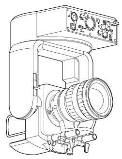
- To protect the lens and the lens connector block of the unit, keep the lens cap and cover on until the lens is attached.
- To prevent lens failure, do not hold the lens parts while working.
- To prevent unit failure, do not hold the camera head while working.
-
Check the ceiling mounting accessories and mounting space.
CIB-PCM1 ceiling bracket kit (option)
Before you start, check that you have the following parts.
- Body bracket (1)
- Ceiling bracket (1)
- Lens release button cover (1)
- Fall prevention wire rope (1)
- +PSW M3×8 screws (9)
- +PSW M4×8 stainless steel screw for fall prevention wire rope (1)
Note
- The fall prevention wire rope is designed to support the unit when suspended. Do not apply any load to it other than the load of the unit.
Mounting space
Refer to the following drawing when determining the mounting location and direction, taking into consideration the space required for turning the lens and the wiring at the rear of the unit.
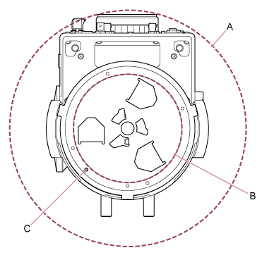
A: Camera head range of movement (e.g. SEL70200GM2 (with SEL20TC attached): Ø370)
B: Ceiling bracket (hole on ceiling side (Ø150))
C: Mounting alignment hole
Note
- Mount on a ceiling (such as concrete) with sufficient strength.
- To mount the unit on a ceiling with insufficient strength, provide sufficient reinforcement.
- Mount it in a stable location that is not subject to vibration. Locations subject to vibration may cause vibration in the image.
- If the unit must be mounted on an inclined surface, keep it within ±15° of the horizontal and take measures to prevent the unit from falling.
- The side opposite the △ hole on the ceiling bracket is the shooting direction (camera front side).
-
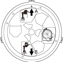
Slide the pan/tilt lock lever to the UNLOCK position to unlock pan/tilt and turn the camera head by 180° in the tilt direction.
-
Slide the pan/tilt lock lever to the LOCK position to lock the pan/tilt of the camera head.
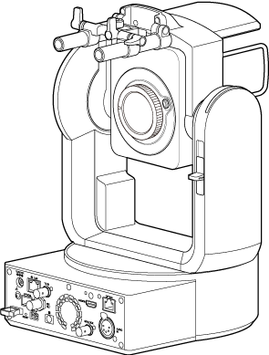
Camera head turned by 180°
Note
- If the camera head pan/tilt does not lock when the lock lever is in the LOCK position, move the camera head manually until it locks in position.
-
Attach the body bracket to the bottom of the unit using the six supplied screws (M3×8).
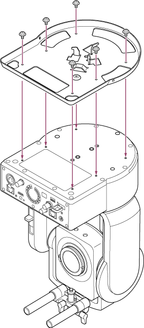

Use the supplied screws. The use of screws other than the supplied screws may damage the interior of the unit.
-
Attach the ceiling bracket to a mounting plate (option), and then attach the plate to the ceiling.
A: Ceiling bracket
B: Ceiling
C: Mounting plate
D: △ hole
Attach the bracket, according to the orientation of the ceiling bracket
Note that when mounted on a ceiling, the front of the camera is on the opposite side of the ceiling bracket in comparison to a normal upright mounting. Mount correctly by referring to the diagram indicating the mounting direction.
A: Front for upright mounting (△ hole orientation)
B: Front for ceiling mounting
Note
- The mounting surface material is the responsibility of the customer.
-
Attach the fall prevention wire rope to the ceiling.
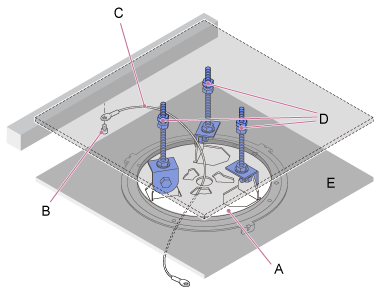
A: Ceiling bracket
B: Hexagon socket head cap screw (M5, 3/16 inch)
C: Wire rope (supplied)
D: Mounting plate
E: Ceiling
-
Pull the fall prevention wire rope through the hole in the center of the ceiling bracket, and attach it to the body bracket.
Route the fall prevention wire rope through the wire rope metal loop of the body bracket and attach it securely to the bracket using the supplied stainless steel screw (M4×8).
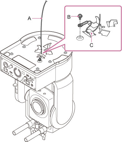
A: Supplied wire rope
B: Supplied Phillips screw (M4×8)
C: Wire rope metal loop
Use the supplied screw. The use of a screw other than the supplied screw may reduce the effectiveness of the wire rope function.
Note
- It is recommended that one person holds the unit as shown in the following diagram while another person mounts the unit.
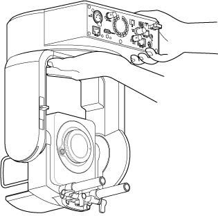
- Do not hold the camera head or lens support while mounting the unit. There is a risk of damage or injury if the unit is dropped or falls.
- Take care when wiring that electrical connectors and cables do not become short-circuited by the fall prevention wire rope.
- The mount can support a suspended mass of up to 8.8 kg (19 lb 6.4 oz) (including the lens). To prevent the unit falling, do not exceed the maximum expected mass.
- It is recommended that one person holds the unit as shown in the following diagram while another person mounts the unit.
-
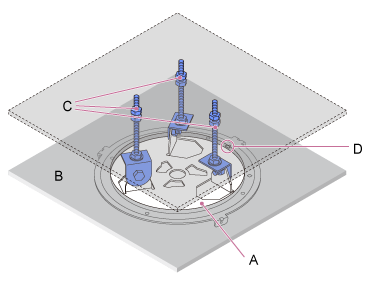
Align the screw hole (A) on the body bracket with the ◇ hole (B) on the ceiling bracket, insert the unit and turn it about 60 degrees clockwise until the screw hole (A) and the screw hole (C) are aligned.
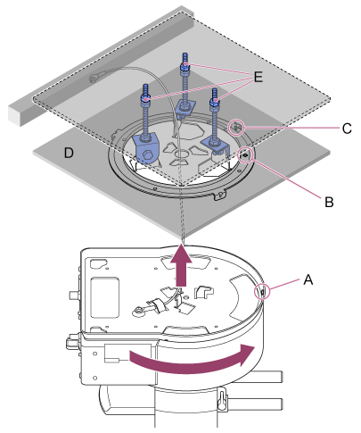
A: Screw hole on the body bracket
B: Screw hole on the ceiling bracket (◇ hole)
C: Screw hole
D: Ceiling
E: Mounting plate
-
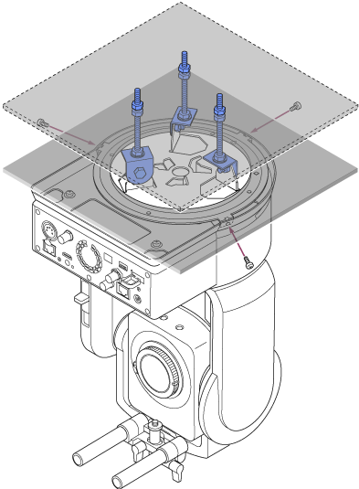
Attach the body bracket and ceiling bracket using the three supplied rotation lock screws (M3×8).
-
Check the mounting status.
Specifically, check the following items.
- Mounting screws are correctly attached.
- Fall prevention wire rope is correctly attached and is not twisted.
- Unit is mounted level (without tilt or wobble).
- Unit does not spin freely when turned.
Next, attach the lens. See “Attaching a Lens,” taking into account the information in “Precautions When Attaching/Removing a Lens,” “Checking the Lens Switches,” and “Precautions When Using a Zoom Lens.”
Note
- To operate the pan/tilt correctly when the unit is mounted on a ceiling, set [Pan-Tilt] > [Direction] > [Ceiling] to [On] in the web menu.
-
After attaching a lens, check that the lens is securely attached.
The lens does not have any protection against falling. Sony can assume no liability for a lens falling from the unit.