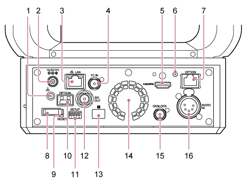
Connector Block
This topic describes the location and function of parts on the connector block of the unit.
-
 (ground) connection
Connect to ground by connecting to the ground terminal of a power outlet or to a grounding bar.
-
DC IN connector (standard DC jack)
Connect to an AC adaptor.
Note
- Do not use any AC adaptor other than the one provided. Connecting another adaptor may cause a fire or malfunction.
-
 LAN (network) connector (RJ-45)
Connect a network cable (category 5e or higher) for network communication and PoE++* power supply.
*PoE++: Power over Ethernet Plus Plus. Conforms to IEEE802.3bt (Type 4 Class 8). For details about connecting, refer to the operating instructions for the power supply device.

Speed LED display status
Indicates the speed of the network connection.
Display Connection speed Not lit 10 Mbps connection 100 Mbps connection Lit orange 1000 Mbps connection Link/ACT LED display status
Indicates the status of the network connection.
Display Connection status Not lit No link Blinking green Link established, data active Lit green Active link Note
- When connecting this product to the Internet, connect via a system that provides a protection function, such as a router or firewall. If connected without such protection, security issues may occur.
-
TC IN connector
Input an external reference timecode signal.
- For details, see “Locking the Timecode to Other Devices.”
-
HDMI connector
Outputs the video from the unit as an HDMI signal.
- For details, see “HDMI OUT connector (Type A connector)” in “Connecting External Monitors and Recording Devices.”
-
HDMI cable retaining plate mounting screw
To prevent the HDMI cable from being removed, attach the supplied HDMI cable retaining plate using the supplied mounting screw (M2.6×6), and attach the HDMI cable using a commercially available cable tie or band.
- For details about attaching the HDMI cable retaining plate, see “Connecting Cables.”
-
OPTION connector
Use to connect a tally signal from an external device or a lens controller.
- For details, see “Connecting a Tally Signal” and “Connecting a Lens Controller.”
-
Cord clamper
Use to secure the AC adaptor cord.
-
RESET switch
Press for at least 5 seconds using the tip of a pen or similar device to reset the settings of the unit to the factory default values.
You can select whether to reset the network connection settings only or all settings using SETUP switch 1.
-
OPTICAL output connector
Outputs an SDI signal converted to optical format when an SFP+ module (option) is connected.
- For details, see “Outputting an Optical Fiber Signal.”
-
SETUP switches

Configures the following settings.
Switch 1: Sets which settings are reset when the RESET switch is pressed.
Setting Description OFF (default) Resets the network connection settings only. The network settings, security settings, and user information (user name and password) of the unit will be reset. ON Resets all settings to factory defaults. Switch 2: Sets whether the +48 V power supply (phantom power) is turned on/off when an audio input device is connected. The setting is applied immediately.
This function is enabled when [Audio] > [Audio Input] > [AUDIO IN Select] is set to [MIC] in the camera menu.
Setting Description OFF (default) Do not supply +48 V power (phantom power supply). Configure this setting when using an external audio device (such as a mixer), dynamic microphone, or microphone with a built-in battery. ON Supply +48 V power (phantom power supply) to a phantom power compatible microphone connected to the AUDIO IN connector (CH-1 or CH-2). Note
- Setting switch 2 to the ON position and connecting a microphone that is not compatible with a +48 V source may damage the connected device. Check the setting before connecting the device.
Switch 3: Enables/disables VISCA over IP communication. The settings are applied when the camera is turned on.
Set to the ON position to use the unit when connected to a remote controller (RM-IP500).
Setting Description OFF (default) Will not respond to VISCA over IP commands. ON Accepts VISCA over IP commands. Note
- If the administrator password has not been configured, VISCA over IP communication is disabled, regardless of the switch setting. For details about configuring the administrator password, see “Initial Setup of the Unit.”
Switch 4: Sets the IP address to a specific value.
Setting Description OFF (default) The user sets the IP address. ON Sets the IP address of the unit to 192.168.0.100 at startup (fixed IP address mode). Note
- If the IP address is changed after startup in the web menu, set this switch to the OFF position.
Hint
- Switch 4 sets the IP address in software version 3.0 and later.
- If using a software version prior to 3.0, this sets the infrared remote control. For details, see [Technical] > [IR Remote] > [Pan-Tilt Speed] in the web menu.
OFF: Pan/tilt operates at normal speed.
ON: Pan/tilt operates at high speed.
-
SDI OUT connector
Outputs the video from the unit as a 12G/6G/3G/HD-SDI signal.
The unit can also be configured for RAW signal output.
- For details, see “SDI OUT connector (BNC type)” in “Connecting External Monitors and Recording Devices.”
-
 Infrared remote control sensor (rear)
Infrared sensor for the supplied infrared remote control.
-
Fan/air outlet
Emits heat from inside the unit.
Note
- Do not cover the air outlet. Doing so may cause a malfunction.
- Note that the area near the air outlet may become hot.
-
GENLOCK connector
Use to input an external sync signal.
- For details, see “Synchronizing the Phase of the Video Signal (Genlock).”
-
AUDIO IN connector (XLR type 5-pin connector)
Use to input the signal from an external microphone or audio device.
It functions as an AUDIO IN CH-1 connector or AUDIO IN CH-2 connector.
- For details, see “Connecting an External Microphone or External Audio Device.”