Attaching a Lens
This topic describes how to attach an E-mount lens or A-mount lens.
Note
- Do not transport the unit with the lens still attached.
- When using an A-mount lens, the iris is set manually and focus is set to MF.
-
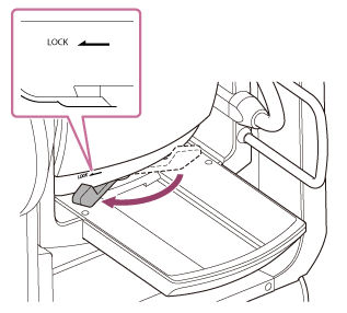
Slide the pan/tilt lock lever to the LOCK position to lock the pan/tilt of the camera head.
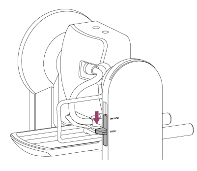
Note
- If the camera head pan/tilt does not lock when the lock lever is in the LOCK position, move the camera head manually until it locks in position.
-
Turn the clamp lever for the lens support pedestal attachment screw counterclockwise to loosen the lock, then move the lens support pedestal attachment screw to a position that does not interfere with the lens.
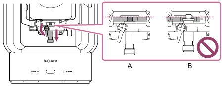
A: Correct
B: Incorrect
-
Turn the camera head lock lever in the direction of the arrow to unlock the camera head.
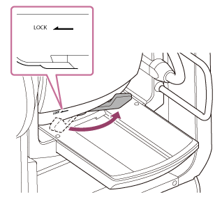
Note
- Until the camera head is locked again, there is a risk that the camera head may move under its own weight. Support the camera head with your hand while performing the task.
-
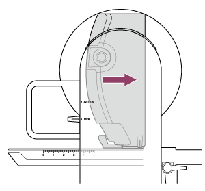
Slide the camera head to the frontmost position.
-
Turn the camera head lock lever in the direction of the arrow to lock the camera head.
Note
- Make sure the camera head lock lever does not come into contact with other parts to avoid interfering with the tilt operation.
-
Remove the cap and cover from the unit and the lens.
-
Align the lens mount mark (white) with the unit, carefully insert the lens into the camera head, and then turn the lens clockwise until it clicks into the locked position.
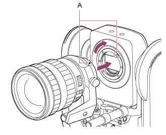
A: Mount marks (white)
Note
- To use an A-mount lens, attach a lens mount adaptor (option) to the unit and then attach the A-mount lens.
-
Turn the camera head lock lever in the direction of the arrow to unlock the camera head.
Note
- Until the camera head is locked again, there is a risk that the camera head may move under its own weight. Support the camera head with your hand while performing the task.
-
Maintain the forward/rearward balance of the camera head so that the slide base is horizontal.
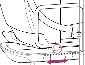
If you are using one of the following lenses, you can roughly balance the unit and lens by referring to the scale on the slide base.
Scale position Lens name 0.5 SEL70200GM (with SEL20TC attached) 1.7 SEL70200GM 2.0 SEL70200GM2 (with SEL20TC attached) 3.0 SELP28135G, SEL70200GM2 3.5 SELP18110G 3.6 SELC1635G 5.0 or higher SEL1224GM, SEL1635GM, SELP1635G, SELP18105G, SELP1020G Note
- While attaching the lens, make appropriate adjustments to the balance so that the unit does not tilt back and forth.
- Adjust the balance on a horizontal surface.
- Remove the lens support unit when using the SELC1635G.
-
Turn the camera head lock lever in the direction of the arrow to lock the camera head.
Note
- Make sure the camera head lock lever does not come into contact with other parts to avoid interfering with the tilt operation.
Confirmation method: Slide the pan/tilt lock to the UNLOCK position, turn the camera block so that it is facing upward by hand, and visually confirm that it is not in contact with other parts. If there is contact, turn the camera head lock lever again in the direction of the arrow.
- Make sure the camera head lock lever does not come into contact with other parts to avoid interfering with the tilt operation.
-
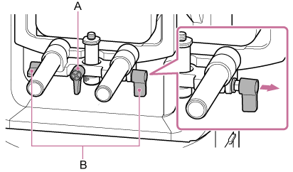
Turn the lens support clamp levers counterclockwise to loosen the lens support unit.
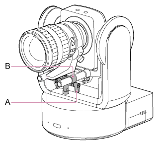
A: Lens support rod clamp lever (2 places)
B: Lens support unit
-
Move the lens support unit so that the lens support pedestal is aligned with the lens support pedestal attachment screw, then turn the screw clockwise to secure the lens support pedestal.
Note
- Make sure the lens support pedestal is perpendicular to the lens support pedestal attachment screw, and then tighten.
-
Turn the clamp lever for the lens support pedestal attachment screw clockwise to lock the lens support pedestal attachment screw.
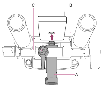
A: Lens support pedestal attachment screw
B: Attachment screw hole
C: Lens support pedestal attachment screw clamp lever
Hint
- If a clamp lever is in a position that makes it difficult to turn, release the clamp lever and rotate it to an angle that will make operation easier. When in the desired position, close the clamp lever.
A: Lens support pedestal attachment screw clamp lever
B: Lens support rod clamp lever
-
Turn the two lens support rod clamp levers clockwise to secure the lens support unit.
-
Check that both levers are tightened and not loose, the lens is attached correctly, and that the lens switches are set correctly.
- If a lever is loose or the lens is not attached correctly, the lens may fall and become damaged.
- When using an E-mount power zoom lens, the lens must also be calibrated separately to accurately restore the zoom positions stored in the camera as preset positions. For details, see “Calibrating an E-Mount Lens.”