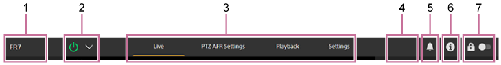
Structure of Common Area of Screens
This topic describes the structure of the common area of screens.
-
Camera name
Displays the name of the camera.
You can change the name using [Network] > [Camera Name] in the web menu.
The background color changes according to the external tally signal.
-
Power switch
When the unit is turned on, a check mark is placed in [Power ON] in the switch menu.
You can press the power switch and select [Power Standby] in the switch menu to set the power supply of the unit to standby state.
In power standby mode, the following screen appears.
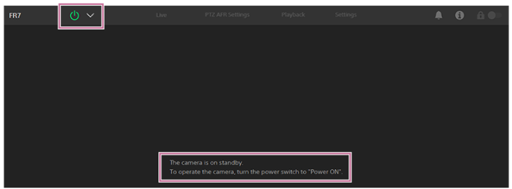
To turn the power on again, press the power switch and select [Power ON] in the switch menu.
-
Operation screen switching tabs
Press a tab to display the corresponding operation screen.
[Live] tab: Display the live operation screen.
[PTZ AFR Settings] tab: Display the PTZ auto framing settings screen.
[Playback] tab: Display the playback operation screen.
[Settings] tab: Display the settings screen (web menu).
-
PoE++ indicator, Abnormal temperature warning
PoE++ is displayed when connected to a PoE++ source. If an abnormal temperature condition arises, the
 (Temperature warning) mark appears.
 -
Notifications mark
When a message arrives, the mark indication changes as shown below.
 (Notifications on)
Take the necessary action according to the message displayed in the camera image panel.
Note
- Messages are not displayed when [Monitoring] > [Output Display] > [HDMI/Stream] is set to [Off] in the web menu. Set to [On] to check the contents of messages.
-
 (Camera status) button
Press the button to display camera recorded image/output image signal information, lens information, and lens controller (option) status on a separate screen.
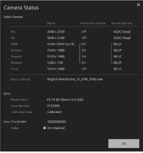
When lens controller (option) related notification occurs, the indication changes as shown below.

-
Screen operation lock switch
 (Operation unlock): Set the switch to the left position to control operations on the live operation screen and playback operation screen.
 (Operation lock): Set the switch to the right position to lock operations on the live operation screen and playback operation screen to prevent accidental misoperation.