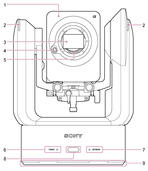
Front View
This topic describes the location and function of parts on the front of the unit.
Hint
- This description refers to the illustration of the unit without an attached lens.

-
Camera head
Note
- Do not subject the camera head to strong impacts.
-
Recording/tally lamp
When configured as a recording lamp, the lamp lights up red when recording to a memory card. The lamp blinks when the remaining free space on the recording media is low or when an error occurs.
- For details, see “Error/Warning Messages.”
When configured as a tally lamp, the lamp lights up red or green according to the external tally signal.
- For details, see “Connecting a Tally Signal.”
When [Technical] > [Tally] > [Tally Control] is set to [PTZ AFR] in the web menu, it displays the auto framing operation status.
- For details, see “Checking the PTZ Auto Framing Status Remotely.”
-
Image sensor
Note
- Do not touch directly with your hands.
-
Lens release button
Press to remove the lens.
- For details, see “Removing a Lens.”
-
Lens signal contacts
Note
- Do not touch directly with your hands.
-
POWER lamp
-
NETWORK lamp
The state of the unit is indicated by the combination of display color and lit status (lit, blinking, not lit) of the POWER lamp and NETWORK lamp.
POWER lamp NETWORK lamp Unit status Lit green*1 Lit green Power-on (network connected) Not lit Power-on (network not connected) Blinking green Not lit Power-on process in progress Lit orange Not lit Power standby state Blinking yellow Not lit Software update in progress Blinking orange slowly*2 Blinking green slowly*2 The unit cannot operate normally. For details, view the system log. If the problem persists even after putting the unit in standby mode or turning the power off and then on again, contact your Sony service representative. Blinking orange rapidly*3 Blinking green rapidly*3 A malfunction occurred in the unit. Contact your Sony service representative. *1Blinks green when a command is received from the supplied infrared remote control.
*2Blinking slowly: Blinking once per second
*3Blinking rapidly: Blinking four times per second
-
Infrared remote control sensor
Receives the control signal from the supplied infrared remote control.
-
Air inlet
Note
- Do not block the air flow. Doing so may cause a malfunction.

